
BUSMASTER standalone operation
During a road test, powertrain and chassis ECUs continuously broadcast status frames. You can save channel settings and a logging task on the analyzer at the workstation, then let it record on the vehicle without a PC. The device can also run saved periodic transmit, routing, and replay tasks.
This guide uses BUSMASTER 3.2.2.52 (Build 585). The X4R screenshots show firmware 2.6.3.1. The screenshots use the Simplified Chinese interface. The steps below give the corresponding English control names.
1 Check which tasks your device supports
Section titled “1 Check which tasks your device supports”Find the row for your model and the physical port you will use. XL2 and XL4 have both CAN and LIN ports.
| Device or port | Periodic transmit or response | CAN hardware routing | Standalone logging | Standalone replay |
|---|---|---|---|---|
| CAN ports on X2R and X4R | Periodic transmit | Between CAN ports on the same device | To a TF card | CAN and CAN FD frames from a TF card |
| CAN port on third-generation X1 | Periodic transmit | One CAN port, so no inter-port routing | Not supported | Short sequences from internal flash |
| CAN ports on third-generation X2, X4, XL2, and XL4 | Periodic transmit | Between CAN ports on the same device | Not supported | Short sequences from internal flash |
| LIN ports on L1, XL2, and XL4 | Periodic master transmit and slave response | Not applicable | Not supported | LIN file replay is not supported |
For other devices, check the model’s power and configuration requirements.
- PCIe X8L4 can store CAN periodic transmit tasks and a small amount of replay data. It still needs power from the PCIe slot.
- GWR supports device-side transmit, routing, logging, and replay. Check which CAN ports and storage are available on your unit.
- F2 runs transmit and gateway tasks through its firmware. Its USB port is for 5 V power only.
Save a CFX project to continue editing on the PC. After configuring a standalone task, use the device save button in the relevant window so the analyzer can run the task after power-up.
2 Connect the bus and save channel settings
Section titled “2 Connect the bus and save channel settings”- Connect the analyzer to the CAN or LIN segment containing the ECU. Set the bitrate and operating mode used by that network. The CAN FD screenshot shows a 500 kbit/s nominal bitrate and a 2 Mbit/s data bitrate. When adding a logger to an already terminated vehicle bus for passive capture, normally leave the analyzer’s termination off. To transmit, use Normal mode and make sure a node on the bus can acknowledge frames.
- On the CAN or LIN tab, open Driver Selection, choose the BUSMUST driver, and open Channel Configuration. In Hardware Selection, select the wired physical port on the left and click
>>. The transmit and routing windows use the logical channel numbers shown on the right. In the CAN screenshot, physical CH1 is logical channel 1. - Select the channel on the right. For CAN, set the mode, termination, bitrate, and sample point. For LIN, set the master or slave role, bitrate, pull-up, and 12 V output. If the LIN bus already has an external master and a 12 V supply, you can configure the analyzer as a slave and turn off its 12 V output as required by the wiring.
- Click Save to device offline storage, check the channel in the confirmation, and click OK. To read back the saved parameters, reopen Channel Configuration and click Load from device offline storage.
- Before saving a task, click Connect on the relevant tab and confirm that the expected frames appear. See CAN transmit and receive or LIN messaging and schedule tables for first-time setup.
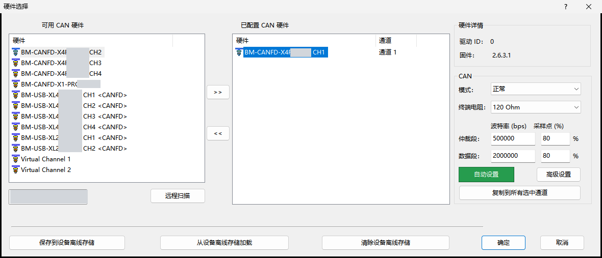
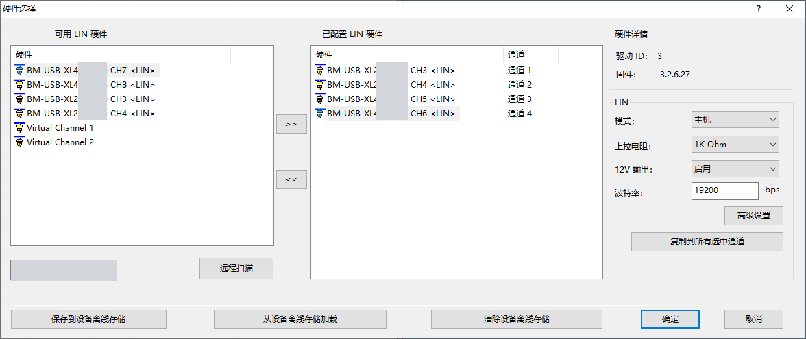
If you are still identifying the frames on the bus, open Channel Configuration → Advanced and let the hardware accept all IDs. Frames dropped by the hardware filter are unavailable for logging or routing on that channel. To filter specific IDs, see CAN FD hardware receive filters or LIN device configuration and messaging.
A USB analyzer still needs power after it is disconnected from the PC. Move its USB cable to a suitable independent 5 V supply and keep the bus wiring in place. On LIN, share a signal ground with the analyzer and provide power and pull-up as required by the network wiring.
3 Send frames periodically without a PC
Section titled “3 Send frames periodically without a PC”3.1 Periodic CAN transmit
Section titled “3.1 Periodic CAN transmit”If an ECU expects an input frame once a second, you can schedule it on the analyzer. The example uses Classical CAN standard ID 0x320. Use the ID and data defined for your ECU.
- Open CAN → Transmit Window and double-click [Add Message]. Select logical channel 1, set the frame type to
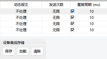
Std, enter ID0x320and a length of 4, and enter01 02 03 04in the data byte view. Set Dynamic Message to No processing and set Send Count to Infinite. - Enter 1000 in Repetition (ms) and select the checkbox to its left. If the CAN network is disconnected in BUSMASTER, click Connect on the CAN tab. Check the ID, data, and interval in the ECU’s diagnostic view or a bus monitor.
- While CAN is connected, click Save in Device Offline Storage at the lower left of the transmit window. Check that the confirmation shows the intended channel.
- Click Disconnect on the CAN tab. If the analyzer will run away from the PC, connect an independent supply as described in section 2. Once the analyzer starts, check that
0x320still appears once a second. See section 5.5 for the X2R/X4R startup delay. - To stop the task, reconnect the analyzer to the PC and connect CAN in BUSMASTER. Clear the frame’s repetition checkbox and click Device Offline Storage → Save again. Check that
0x320stops after the device returns to standalone operation.
For CAN FD, choose the FD frame type and BRS setting required by the project. Keep BUSMASTER running for tasks that depend on the PC, such as limited send counts, changing payloads, E2E protection, or custom algorithms. See Transmit test patterns and message send count.
3.2 Periodic LIN master transmit and slave responses
Section titled “3.2 Periodic LIN master transmit and slave responses”Send a periodic frame as a master. In this example the analyzer sends a LIN control frame once a second. With Master Write, it sends both the header and the data.
- In LIN → Channel Configuration, select Master. The example uses 19200 bps and a 1 kΩ master pull-up. Enable the 12 V output if the analyzer is supplying the LIN network and the wiring calls for it.
- Add a frame in LIN → Transmit Window. Select logical channel 1 and
Master Write. Enter ID0x12, length 4, and data01 02 03 04. Set the checksum type toEnhanced. - Set Test Pattern to Disabled and Send Count to Infinite. Enter 1000 ms and select the repetition checkbox. Confirm that LIN is connected and the receiving node sees the frame, then click Device Offline Storage → Save.
- Disconnect LIN and move the analyzer to an independent supply. Check the frame ID, data, and interval at the receiver. To stop the task, reconnect LIN, clear the repetition checkbox for this row, and save to the device again.
Respond as a slave. If the network already has a LIN master, the analyzer can return data after it receives the matching frame header.
- In LIN → Channel Configuration, select Slave. Set the bitrate, pull-up, and power to suit the existing network.
- In LIN → Transmit Window, add a
Slave Writeframe. If the external master requests ID0x12, enter that ID and configure the response length, data, and checksum required by the master. Select the checkbox for the row to enable the response. - Connect LIN and click Device Offline Storage → Save. After switching to an independent supply, have the external master send the header for ID
0x12, then check the response length and data. To stop responding, reconnect LIN, clear the checkbox, and save. Use Load in the transmit window to read back saved tasks.
To send multiple slots from an LDF schedule, load the LDF, choose the master ECU and active table, and connect LIN. You can store the schedule and its transmit rows in the CFX project. Follow LIN messaging and schedule tables for that workflow.
4 Route CAN frames without a PC
Section titled “4 Route CAN frames without a PC”To send powertrain ECU status frame 0x123 to a separate acquisition network, use an analyzer that supports hardware routing. On an X4R, connect CH1 to the powertrain CAN network and CH2 to the acquisition network. Set the bitrate and termination for each segment and make sure the acquisition network has a node that can acknowledge frames.
4.1 Forward one ECU frame to the acquisition network
Section titled “4.1 Forward one ECU frame to the acquisition network”-
Map CH1 and CH2 to logical channels 1 and 2 and save their parameters as described in section 2. Click Connect on the CAN tab. In the message window, check that standard frame
0x123reaches logical channel 1. -
Open CAN → BUSMUST Advanced Features → Message Route. Click Add, then double-click the relevant cells and enter the following values.
Type Source Target Message Type Id Mask/Source Id Value/Target UNICAST12STD0x7FF0x123 -
Keep CAN connected, select the checkbox in Index, and click Save to device. Click Disconnect on the CAN tab. Allow about 10 seconds for an X2R/X4R to switch to standalone operation. Check the payload and period of
0x123on the acquisition network. Other source IDs, such as0x124, do not match this rule. -
To stop forwarding this frame, reconnect the analyzer to the PC and connect CAN. Clear the row’s checkbox or delete the row, then click Save to device. Disconnect and confirm on the acquisition network that the frame is no longer forwarded.

4.2 Fill in the routing fields
Section titled “4.2 Fill in the routing fields”| Column | How to use it |
|---|---|
| Index | The checkbox beside the row number enables the rule. A new row is unchecked, so you can enter its settings first. |
| Type | Select one of the routing types in section 4.3. |
| Source / Target | Enter the BUSMASTER logical channels that receive and forward the frame. With BROADCAST, you can select more than one target. |
| Message Type | For unicast, broadcast, or ID-only changes, select the incoming frame type, for example STD, EXT, STD-FD, or STD-FD-BRS. ALL accepts every frame type. When converting the frame type, select the direction, for example STD -> STD-FD. |
| Id Mask/Source | For rules that keep the ID, enter a mask. Use 0x7FF for an exact standard-ID match and 0x1FFFFFFF for an exact extended-ID match. The rule checks (received ID & mask) = ID value. For ID MAP and ID&TYPE MAP, enter the complete source ID in this column. |
| Id Value/Target | Enter the value used with the mask. For ID MAP and ID&TYPE MAP, enter the new ID to transmit. |
Up and Down move a rule in the list. Delete removes it. If rules overlap, check which ones the same frame can match to avoid sending duplicates to a target. Load from device reads the saved rules, and Clear device clears the device’s routing table. To stop only one rule, edit that row and save.
4.3 Routing types
Section titled “4.3 Routing types”| Type | What it does | When to use it |
|---|---|---|
UNICAST |
Forwards matching frames unchanged to one target channel. | Pass a status frame or a masked group of frames from the powertrain network to a data logger. |
BROADCAST |
Forwards matching frames unchanged to several channels. | Send the same status frame to a diagnostic network and an acquisition network. Select both ports under Target. |
ID MAP |
Matches one source ID and forwards the frame under a new ID while preserving its type and data. | The two networks assign different IDs to the same message. |
TYPE MAP |
Converts the frame type in the direction selected under Message Type. | Route between Classical CAN and CAN FD while using the same standard ID. |
ID&TYPE MAP |
Changes both the ID and the frame type. | The target network uses a different ID and requires an incoming Classical CAN frame to be sent as CAN FD. |
A mask can cover a contiguous group of IDs that you want to forward unchanged. For example, 0x7F8 under Id Mask/Source, 0x120 under Id Value/Target, and STD under Message Type match standard IDs 0x120–0x127. To assign different target IDs, add one rule per frame as shown in section 4.5.
4.4 Route in both directions between CAN FD and Classical CAN
Section titled “4.4 Route in both directions between CAN FD and Classical CAN”A powertrain ECU sends standard ID 0x321 as an eight-byte CAN FD frame with BRS. A Classical CAN display needs that status frame and sends an eight-byte standard request, 0x322, back to the ECU. The two networks use the same IDs for those messages.
-
On one analyzer that supports hardware routing, connect CH1 to CAN FD and CH2 to Classical CAN. This example uses 500 kbit/s nominal and 2 Mbit/s data on CH1, and 500 kbit/s on CH2. Map the ports to logical channels 1 and 2 and save both channel settings.
-
Add both
TYPE MAPrules. The last two columns specify the mask and match value.Direction Type Source Target Message Type Id Mask/Source Id Value/Target CAN FD → Classical CAN TYPE MAP12STD-FD-BRS -> STD0x7FF0x321Classical CAN → CAN FD TYPE MAP21STD -> STD-FD-BRS0x7FF0x322 -
Click Connect on the CAN tab, enable both rules, and click Save to device. Click Disconnect. Once the analyzer is running on its own, check for an eight-byte
0x321frame on Classical CAN and an eight-byte0x322frame with BRS on CAN FD. Compare the payload bytes with the original frames.
For CAN FD frames without BRS, select STD-FD -> STD or STD -> STD-FD as required by the source and target. Classical CAN carries up to eight data bytes per frame. For longer FD payloads, check the forwarding behavior of your firmware and how the target ECU expects to receive the data.
4.5 Forward three selected frames with new IDs
Section titled “4.5 Forward three selected frames with new IDs”The acquisition network needs only vehicle speed, brake status, and torque status from the powertrain CAN network. It uses different standard IDs for these messages and keeps their data layout. Both networks use Classical CAN.
-
Connect CH1 on the analyzer to the powertrain CAN network and CH2 to the acquisition network. Map them to logical channels 1 and 2, then save the settings for both channels. Check each network’s communication matrix to confirm the ID assignments.
-
In Message Route, create one
ID MAPrule per frame. Each rule uses one hardware route on the source channel. Fill in its original ID under Id Mask/Source and its new ID under Id Value/Target.Message Type Source Target Message Type Id Mask/Source Id Value/Target Vehicle speed ID MAP12STD0x1800x280Brake status ID MAP12STD0x1830x283Torque status ID MAP12STD0x1A00x2A0 -
Click Connect on the CAN tab, enable all three rules, and Save to device. Click Disconnect. In standalone operation, verify
0x280,0x283, and0x2A0on the acquisition network and compare each payload. Other source IDs, such as0x182, do not match these rules.
For routing across devices or composing outgoing messages from signals, see BUSMUST advanced features.
5 Log traffic on an X2R/X4R and export the files
Section titled “5 Log traffic on an X2R/X4R and export the files”To review powertrain and chassis ECU behavior after a road test, connect the logger to the relevant CAN networks and record to its TF card. X2R/X4R support cards up to 128 GB formatted as FAT16, FAT32, or exFAT. Back up existing configurations and logs before reusing a card.
5.1 Configure offline logging
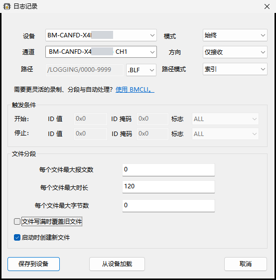
Section titled “5.1 Configure offline logging”Save the channel settings as described in section 2 and connect CAN. In the message window, check that the target ECU’s frames are coming in. The example below shows standard ID 0x123 on powertrain CAN. Open CAN → BUSMUST Advanced Features → Offline Logging.

| Control | How to use it |
|---|---|
| Device | Select the logger that holds the TF card. When multiple devices appear, check the model and which unit has the card. |
| Channels | Select the CAN ports connected to the networks you need. To log powertrain and chassis CAN together, select both ports. |
| Mode | Always records continuously in standalone operation. Triggered starts and stops on the conditions below. Disabled turns off the task. |
| Direction | Rx Only captures frames received by the logger, including both an external flash programmer’s requests and the ECU’s responses. Tx Only captures frames the logger transmits. Rx & Tx shows both sides of device routing or transmission. |
| Path | Shows the LOGGING directory on the card and the current naming pattern. Choose the PC archive folder when copying the log. |
| File format (next to Path) | .BLF suits long or multi-channel recordings. .ASC is plain text and is convenient for short captures. |
| Path Mode | Fixed uses the name 0000 for a short capture. Copy it to the PC before starting another. Index assigns four-digit numbers. Time names files using the device clock, which you should check before recording. |
| Start / Stop → Id Value | In Triggered mode, set the CAN IDs used to start and stop logging. After a stop, the logger can wait for the next start match. |
| Start / Stop → Id Mask | Specifies which ID bits to compare. Enter 0x7FF for an exact standard-ID match or 0x1FFFFFFF for an exact extended-ID match. Check which frames match before using a mask for multiple IDs. |
| Start / Stop → Flags | Select STD for standard Classical CAN or EXT for extended Classical CAN. Choose the CAN FD frame type with or without BRS as needed. ALL applies the ID condition to any frame type. |
| Max Messages Per File | Start a new file after this many messages. For example, 100000 splits the log every 100,000 messages. |
| Max Seconds Per File | Set the file duration in seconds. At 600, the logger starts a new file about every 10 minutes and continues recording. |
| Max Bytes Per File | Split at a byte threshold. For example, 268435456 is 256 MiB. Final file size also depends on format and compression. |
| Overwrite Old File On Full | Lets the logger replace old logs when storage fills up. To preserve a complete flash programming session or fault capture, clear this checkbox and leave enough space on the card. |
| Create New File On Start | Starts a separate file for each startup or start trigger. Use Index or Time to distinguish recordings. |
| Save to device / Load from device / Cancel | Save writes the task to the device. Load reads its saved settings. Cancel closes the window. |
Set each segmentation threshold separately. A value of 0 leaves that condition inactive. When several conditions are active, meeting any of them starts the next file. For example, with both time and size thresholds, high traffic can start a new file before the time limit. Use Index or Time for split recordings.
5.2 Keep recent logs during a long road test
Section titled “5.2 Keep recent logs during a long road test”Select the powertrain or chassis CAN ports you need. If existing nodes acknowledge frames, you can use Listen Only on the logger and set its termination according to the vehicle wiring. Select Always, Rx Only, and BLF. Use Time to find files by date and time or Index to find them by sequence.
Set Max Seconds Per File to 600. If the files get too large, also set a limit of 268435456 bytes, leaving the message count at 0. Select Create New File On Start and Overwrite Old File On Full.
Try the settings over several representative parts of the drive, then estimate the hours you can keep from the file sizes and free card space. After a fault occurs, copy the relevant files promptly so later traffic does not overwrite them.
5.3 Capture a UDS flash programming session with triggers
Section titled “5.3 Capture a UDS flash programming session with triggers”Connect the logger to the CAN segment shared by the flash programmer and the target ECU. If the programmer can send marker frames, send a start marker before its first diagnostic request and a stop marker after programming and the post-reset checks. The example uses 0x6A0 and 0x6A1. Use the IDs assigned at your workstation and keep them distinct from other traffic on the same logger.
| Option | Example setting |
|---|---|
| Mode, direction, and format | Triggered, Rx Only, and BLF |
| Start condition | Id Value 0x6A0, Id Mask 0x7FF, Flags STD |
| Stop condition | Id Value 0x6A1, Id Mask 0x7FF, Flags STD |
| Naming and segmentation | Choose Index or Time, select Create New File On Start, and clear Overwrite Old File On Full. With enough free space, you can leave all three thresholds at 0. For a long session, split by time and keep all files from that session. |
Check that the log includes the first request, the ECU response, and the last check you need. For a programming failure, inspect the requests, responses, and timing before the error.
The trigger checks CAN ID, mask, and frame flags. A diagnostic ID can carry several UDS services. The trigger has no option to match the service byte. If your workstation cannot send dedicated marker frames, select Always before programming and note the start and end times. Use the time range and diagnostic IDs to find the session in the log.
5.4 Capture intermittent ECU status timeouts
Section titled “5.4 Capture intermittent ECU status timeouts”If a steering ECU status frame times out occasionally, select its CAN port and set the mode to Always and direction to Rx Only. For a short recording, use ASC to inspect individual frames or copy relevant lines into a diagnostic report.
Choose Index, set the message count to 100000, and leave time and bytes at 0. Clear the overwrite checkbox and select Create New File On Start. Use the file sequence and fault time to locate the status frame, then compare the intervals before and after the timeout. If the fault crosses a file boundary, inspect the adjacent files together.
5.5 Start logging and copy the files
Section titled “5.5 Start logging and copy the files”- In Offline Logging, click Save to device. Click Disconnect on the CAN tab. To move the logger to the vehicle, connect its USB cable to an independent 5 V supply. Allow about 10 seconds for X2R/X4R to enter standalone mode. For a triggered recording, wait for the device to switch modes before running the flash programmer.
- When the capture is complete, reconnect the logger to the PC and click Connect on the CAN tab. Open Offline Logging, click Load from device, set the mode to Disabled, and click Save to device. If offline replay is also enabled, disable it and save in its own window.
- Wait for the device to finish writing. Windows may hide the card’s drive letter while logging or replay is active. If the drive still does not appear after disabling and saving these tasks, power the logger again through USB and open File Explorer.
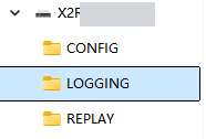
- Open the TF card and copy the files from
LOGGINGto the PC. Follow Logging, import, and replay formats to open the log. Find the traffic by time and channel, then check the ID, data, and intervals.
6 Replay CAN frames without a PC
Section titled “6 Replay CAN frames without a PC”To deliver recorded CAN or CAN FD traffic to an ECU again, use a TF card or internal flash according to your model. Check which CAN port you will use and which channel the log contains. To reproduce LIN communication, use a transmit task from section 3.2 or a LIN schedule table.
6.1 Replay from an X2R/X4R TF card
Section titled “6.1 Replay from an X2R/X4R TF card”- Save the replay port’s settings as described in section 2. Prepare a short log whose channel number matches the physical port you want to use. A CH1 receive log copied to the PC in section 5 works for this example.
- In Windows File Explorer, copy the file to
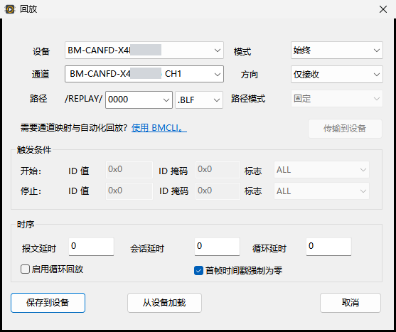
REPLAYon the TF card. Give it an unused four-digit filename such as0000.BLF. If the name already exists, pick another number. The TF workflow accepts.BLFand.BBD. - Open CAN → BUSMUST Advanced Features → Offline Replay. Select the device and CH1. Enter
0000as the path index and choose.BLF. Set mode to Always and direction to Rx Only. CH1 frames marked as received in the log will be transmitted on physical CH1. - For the first run, leave Enable Cyclic Replay unchecked, enter
0in all three delay fields, and select Force Zero Timestamp On First Message. Click Save to device, then Disconnect on the CAN tab. Allow about 10 seconds when switching to standalone operation or powering the device back on. - In the ECU diagnostics or a bus monitor, check the first and last frames and the intervals between them. Once a single pass works, select Enable Cyclic Replay and save again if you want continuous playback.
- To stop, reconnect the device to the PC and connect CAN. In Offline Replay, select Disabled and click Save to device. Return to standalone operation and check that the playback frames have stopped.
6.2 Replay from a third-generation device’s internal flash
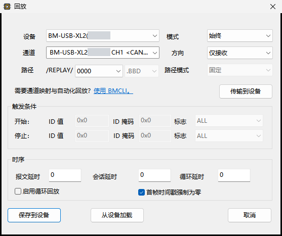
Section titled “6.2 Replay from a third-generation device’s internal flash”- Save the CAN channel settings and open Offline Replay. Select the device and CAN channel, then select
0000as the path. The.BBDextension shown here is the device’s internal format. - Click PC to device and select a short CAN log. The picker accepts LOG, ASC, BBD, and BLF. BUSMASTER converts the log to a sequence the device can play. If it is too large, extract a shorter segment and try again.
- When Download completed appears, check the channel, direction, and mode. For the first run, select Always and leave the three delays at
0. Enable looping if needed and click Save to device. - Click Disconnect on the CAN tab, connect an independent supply, and check the sequence and timing in a bus monitor. Power-cycle the device to check whether replay resumes from the saved configuration. Path
0000keeps the sequence across power loss. Data in<RAMBUF>is cleared on power loss. - To stop, reconnect the device to the PC and connect CAN. Set Offline Replay to Disabled and save. After power-up, check that the frames are no longer being played.
6.3 Common replay settings
Section titled “6.3 Common replay settings”| Control | How to use it |
|---|---|
| Device / Channels | Select the analyzer and the CAN port that will transmit the replay frames. Match the physical port to the channel number in the recording. |
| Path / File format / Path Mode | For TF cards, use the fixed path with the four-digit number and extension of the file in REPLAY. For internal flash, select 0000. The device uses .BBD internally. |
| PC to device / Device to PC | Devices with replay buffers can receive a file from the PC or export replay data. For an X2R/X4R TF card, copy files using its Windows drive letter. |
| Mode / Trigger | Always starts playback in standalone operation. Triggered waits for a matching CAN frame to start or stop. Use the ID, mask, and flags described in section 5.1. Disabled turns off replay. |
| Direction | Filters source frames by their Rx and Tx labels. Select Rx Only to replay the frames that the logger originally received from the ECU. |
| Msg Delay / Session Delay / Cycle Delay | Set delays between messages, sessions, and cycles, in milliseconds. Leave all three at 0 to use the recorded timing. When using nonzero values, verify the intervals with your device and firmware. |
| Enable Cyclic Replay / Force Zero Timestamp On First Message | Enable looping to repeat the sequence. When replaying an excerpt from a long log, you can use the first frame in the excerpt as time zero. |
| Save to device / Load from device | Once the replay file is in place, save the mode, channel, and direction. Use Load from device to view the saved configuration. |
7 Troubleshooting
Section titled “7 Troubleshooting”| Symptom | What to check |
|---|---|
| The save button is disabled or the device is missing | Check the driver, channel mapping, and features supported by your model. To save a transmit task, first click Connect on the CAN or LIN tab. |
| Frames are sent when the PC is connected but stop in standalone operation | Check the independent supply. Confirm that both the channel parameters and the transmit task were saved. For periodic tasks, select the repetition checkbox and make sure a node on the bus acknowledges frames. |
| No response from the LIN slave | Send the matching ID from the external master. Check slave mode, the response checkbox, bitrate, checksum, and LIN power. |
| The target network receives no forwarded frames | Confirm that both logical channels map to the same device and that the rule is enabled. Then check the source port’s receive filter, frame type, and ID match. |
| X2R/X4R log is empty or the TF card drive is missing | For an empty log, verify that the message window shows traffic on the selected port. To copy files, stop the relevant tasks and restore the drive as explained in section 5.5. |
| TF replay sends no frames on the selected channel | Check the source log’s channel and Rx or Tx direction, then the file number and extension on the card. If they match, check the bus speed and acknowledgement. |
| Flash replay produces no frames after power-up | Check that you selected 0000 before transferring the file and clicked Save to device after the download. |
| An old task starts again after power-up | Open its window, clear or disable the task, and save to the device. Return to standalone operation and confirm that the task has stopped. |
When contacting support, include the full device model, software version and build, firmware version, screenshots of the settings, and a sample of the frames. Include support logs from the time of the fault if available.
Use the download center for current and archived BUSMASTER releases.