
BUSMASTER E2E: Use DBC signals for protection fields
Use the P01 frame from chapter 01. Before changing its settings, disconnect CAN and clear Repetition. Restore 0x2A0, eight bytes, P01 / BOTH, DataID 0x0123, first counter 0, counter 8 / 4 / Intel and checksum 0 / 8 / Intel.
1. Load the teaching DBC
Section titled “1. Load the teaching DBC”Download E2E_P01.dbc and add it to the CAN project using Database on the CAN ribbon. See the CAN FD and DBC workflow.
Return to the transmit window and select 0x2A0. It may be named E2E_P01_Message. Signal Details should show these entries.
| Signal | Start bit / width / byte order | Role |
|---|---|---|
| Checksum | 0 / 8 / Intel | P01 CRC |
| AliveCounter | 8 / 4 / Intel | P01 counter |
| CommandValue | 16 / 16 / Intel | Application value, initially 0 |
If the signals are absent, check that the DBC is loaded into this project and the row uses standard ID 0x2A0 with an eight-byte payload.
2. Select sources for the counter and checksum
Section titled “2. Select sources for the counter and checksum”- Open E2E below the selected transmit row.
- In Counter → Source, select AliveCounter.
- In Checksum → Source, select Checksum.
- Verify that the counter is 8 / 4 / Intel and the checksum is 0 / 8 / Intel.
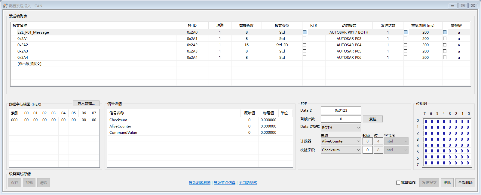
Figure 5. A wide transmit window shows Signal Details and E2E side by side. After selecting a signal, its layout determines the start bit, width and byte order. The derived fields are read-only.
The active algorithm filters available sources. In this exercise, the 8-bit Checksum is eligible for the checksum field. The 16-bit CommandValue is not. Choose Manual when no DBC is loaded. If you change both sources, complete both selections and check the final layout for incorrect widths, overlap and fields outside the payload.
3. Verify the application value and protected payload
Section titled “3. Verify the application value and protected payload”Confirming an unchanged configuration continues the count. To start from the configured first counter, stop periodic transmission and click Reset.
With CommandValue=0, the other application bytes zero and a first counter of 0, use the four reference payloads from chapter 01 after reset. If you change the application value, the CRC changes because E2E uses the updated application payload. The data editor and Signal Details show the application template. Check the counter and CRC in the transmitted or received payload.
4. Work without a DBC or update a signal
Section titled “4. Work without a DBC or update a signal”- With no DBC, leave both sources set to Manual and enter the positions permitted by the profile.
- If a signal does not fit the profile, check the frame length, width, byte order and header position.
- If a DBC signal definition changes, reselect it in Source and check the derived fields even if its name stays the same.
- To return to manual layout, select Manual, edit the allowed fields and press Tab.
Intel and Motorola layouts use different start-bit conventions. Compare the physical bits occupied by each field.
Previous: Select a profile · Series overview · Next: DLL examples
Use the download center for current and archived BUSMASTER releases.