
BUSMASTER E2E: Send your first protected frame
Use AUTOSAR P01 / BOTH to send four frames and verify their full payloads. The transmit window inserts the counter and CRC as it sends each frame.
1. Set up the CAN connection
Section titled “1. Set up the CAN connection”| Item | Example setup |
|---|---|
| BUSMASTER | 3.2.2.51 (Build 571). The screenshots use the Chinese interface. |
| Transmit interface | On the CAN ribbon, use Driver Selection and Channel Configuration to map the logical channel to the wired port. |
| Receiver | Use a separate wired CAN interface or an ECU that receives frames with the same E2E parameters. |
| Bus | Classical CAN at 500 kbit/s. Connect CAN_H, CAN_L and the reference ground as specified by the interfaces. Terminate the bus according to its topology. |
The example uses CH1 on an X1 PRO to transmit and CH1 on a second X1 to receive. Both are in normal mode with one 120 Ω termination at each end. The transmit logical channel is 1. The configured CAN FD data rate of 2 Mbit/s is unused by these Classical CAN frames. Use the channel mapping and termination for your own setup.
Keep CAN disconnected while configuring the frame. You can complete this exercise with the built-in algorithm and manual field layout.
2. Open the transmit window
Section titled “2. Open the transmit window”
Figure 1. The left button shows Connect while CAN is disconnected. It is disabled until a driver and channel are configured. Open Transmit Window to configure the frame. Use the E2E button next to Database when you need to manage the list of available algorithms.
3. Add a Classical CAN frame
Section titled “3. Add a Classical CAN frame”In Configure Transmit Messages – CAN, double-click Double-click to add a message in the transmit list.
| Setting | Value |
|---|---|
| Frame ID | 0x2A0 (11-bit standard ID) |
| Channel | The mapped transmit channel, logical channel 1 in this exercise |
| Payload length | 8 bytes |
| Frame type | Std |
| RTR | Cleared |
| Send Count | 1 |
| Repetition | Cleared |
| Payload | 00 00 00 00 00 00 00 00 |
With the teaching DBC loaded, the frame may be named E2E_P01_Message. Both displays refer to the same CAN ID.
4. Select and configure P01
Section titled “4. Select and configure P01”In the frame’s Dynamic Message list, select AUTOSAR P01 / BOTH.
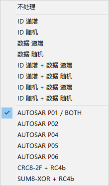
Figure 2. A frame uses one dynamic processing option at a time. Selecting E2E replaces the frame’s ID or payload test pattern.
Select the transmit row and open E2E below it. At the default width, use the tabs to switch between Signal Details and E2E. A wider window displays both side by side.
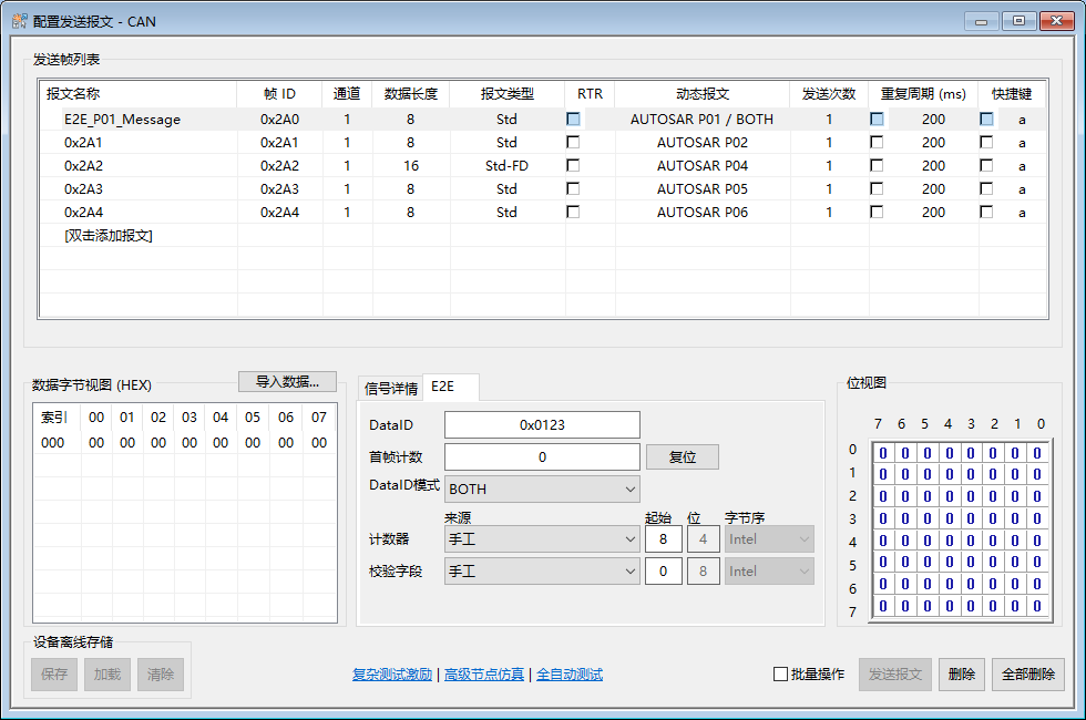
Figure 3. Set the fields as follows.
| Parameter | Value |
|---|---|
| DataID | 0x0123 (hex) |
| First counter | 0 |
| DataID mode | BOTH |
| Counter source | Manual, start bit 8, width 4, Intel |
| Checksum source | Manual, start bit 0, width 8, Intel |
Press Tab to commit text edits and confirm dropdown choices. The software validates each edit as you finish it. If an edit is rejected, check the restored value, then correct the DataID, bit positions or payload length. If you are moving both fields, finish both edits and verify the layout before switching rows or sending.
5. Send four frames
Section titled “5. Send four frames”- Click Connect on the CAN ribbon and start reception on the peer.
- Select
0x2A0in the transmit window and leave Repetition cleared. - Click Send Message once. Check the received ID, channel, frame type and eight payload bytes.
- Click Send Message three more times with the connection and configuration unchanged.
| Frame | Complete payload (hex) | Counter |
|---|---|---|
| 1 | CC 00 00 00 00 00 00 00 |
0 |
| 2 | 91 01 00 00 00 00 00 00 |
1 |
| 3 | 76 02 00 00 00 00 00 00 |
2 |
| 4 | 2B 03 00 00 00 00 00 00 |
3 |
Byte 0 holds the CRC, and the low four bits of byte 1 hold the counter. The data editor continues to display the all-zero payload template. Check the protected output on the receiver. Use these reference values only with the above parameters and template.
6. End the exercise
Section titled “6. End the exercise”Stop reception and disconnect CAN. Reconnecting initializes the counter from the configured starting value. See periodic transmission and reset for the other ways to continue or restart the count.
Series overview · Next: Select a profile
Use the download center for current and archived BUSMASTER releases.