LIN messaging and schedule tables
This guide is for engineers who use BUSMASTER with a BUSMUST USB-LIN analyzer to monitor a bus, transmit and receive messages, analyze signals, record logs, and test schedules.
The full illustrated Chinese article is also available from the BUSMUST WeChat account: LIN messaging and schedule tables.
BUSMASTER provides a dedicated LIN workspace. Driver and hardware-channel configuration, Message Window, Transmit Window, Signal Watch, Logging, and Schedule Configuration all follow the LIN master/slave communication model. The screenshots use a BM-USB-XL4, but the main workflow is the same for the L1, XL2, and other BUSMUST products with LIN capability.
1. Connect the analyzer and select the driver and channel
Section titled “1. Connect the analyzer and select the driver and channel”This example uses a BUSMUST BM-USB-XL4. Connect the device to the computer, then connect LIN, GND, and the required bus supply.
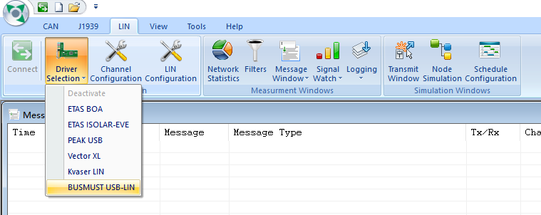
Open Driver Selection on the BUSMASTER LIN ribbon and select BUSMUST USB-LIN. Next, open Channel Configuration and map each detected physical LIN channel to a BUSMASTER logical channel. Names such as Channel 1 and Channel 2 are the logical channel numbers shared by Message Window, Transmit Window, and Logging.
1.1 Master or Slave mode
Section titled “1.1 Master or Slave mode”Mode does not affect passive monitoring. As long as the analyzer does not transmit, either Master or Slave mode can capture traffic already present on the bus.
Mode determines how the analyzer participates in communication and which tasks are available in Transmit Window:
Mastersupports Master Write, Master Read, and Sync Break, and can run a master schedule through Schedule Configuration.Slavesupports Slave Write entries that form a predefined slave response table.
For monitoring an existing network only, start with Slave mode. It also supports automatic bitrate detection, which can help reveal bus activity when the initial bitrate is uncertain. Set the verified bitrate explicitly for formal testing.
1.2 Pull-up selection
Section titled “1.2 Pull-up selection”A LIN master requires a pull-up. Enable the analyzer’s 1K Ohm pull-up when it acts as Master.
When the analyzer acts as Slave on a network with only a few nodes, the 1 kΩ pull-up may be enabled. If several slave nodes already contribute parallel pull-ups, disable the analyzer pull-up to avoid making the total pull-up too strong.
1.3 When to enable 12V Output
Section titled “1.3 When to enable 12V Output”When 12V Output is enabled, the analyzer’s internal supply powers its LIN transceiver and can provide bus-side voltage to other low-current LIN communication devices.
If an existing network already provides 12 V, especially when the analyzer acts as Slave, normally disable the analyzer output and use the external bus supply.
The supply pin is intended only for the LIN PHY and other low-current LIN communication devices. Its maximum output current is 100 mA. Do not use it to drive motors, lamps, or other power loads.
| Typical setup | 12V Output | External 12 V | 1 kΩ pull-up |
|---|---|---|---|
| Analyzer is Master and the bench has no other supply | On | Not connected | On |
| Existing LIN network is already powered | Off | Connected | Set according to the analyzer role |
| Analyzer is Slave and the external Master supplies the bus | Normally off | Connected | May be on with few nodes; off is recommended with many nodes |
1.4 Bitrate and receive range
Section titled “1.4 Bitrate and receive range”Set Baudrate to match the target network. This example uses 19200 bps.
Most applications do not require a hardware receive filter. BUSMASTER receives all LIN identifiers by default. Open Advanced -> Hardware Acceptance Filter and inspect IDs 0 through 63 only when bus load requires hardware filtering or when troubleshooting a missing identifier.
2. Monitor existing traffic in Message Window
Section titled “2. Monitor existing traffic in Message Window”After configuring the channel, select Connect and observe traffic in Message Window.
All LIN communication is initiated by a Master. During monitoring, BUSMASTER can capture both the request sent by the Master and the response returned by a Slave.
Useful Message Window fields include:
Time: when the message appeared.Message: the frame name when an LDF is loaded; otherwise use the identifier.Message Type: a LIN Message, Sync Break, or another LIN event type.Tx/Rx: direction from the current analyzer’s point of view.Channel: the BUSMASTER logical channel.DLC,ID,Checksum, andData Byte(s): the frame contents.
Tx/Rx is relative to the analyzer and is not the same as the Master Write or Master Read operation name:
- A Master Write initiated by this analyzer is Tx.
- A Master Read initiated by this analyzer is also Tx because this analyzer sends the request header.
- A request observed from another Master is Rx.
- A Slave response transmitted by this analyzer is Tx.
Without an LDF, BUSMASTER still displays the identifier, DLC, payload, and checksum. This is sufficient for raw monitoring, initial investigation of an unknown network, and identifier-based troubleshooting.
3. Load an LDF when signal-level analysis is required
Section titled “3. Load an LDF when signal-level analysis is required”An LDF is not required for basic LIN messaging, Logging, or log import. It makes raw identifiers and payloads easier to understand and enables signal-level analysis, signal-value editing, and schedule configuration.
An LDF provides:
- frame names and identifier mappings;
- the Publisher of each frame;
- signal position, length, scaling, and physical values;
- LIN node definitions; and
- Schedule Tables already defined for the network.
A basic LIN module may focus on identifiers and hexadecimal payloads. With a BUSMUST LIN analyzer, BUSMASTER, and an LDF, Message Window, Signal Watch, Transmit Window, and Schedule Configuration share one database definition, reducing manual lookup and payload encoding.
3.1 Sources of an LDF
Section titled “3.1 Sources of an LDF”An LDF normally comes from one of two sources:
- The vehicle manufacturer or project owner supplies an LDF created for the network.
- The project owner supplies a communication matrix, and a development or test engineer creates the LDF from it.
BUSMASTER includes an LDF Editor for creating and editing LDF files. Professional LDF editors from Vector and other vendors can also be used. LDF is a standard LIN database format, so a file created in one compatible tool can be used by other compatible analysis software.
3.2 Load the LDF
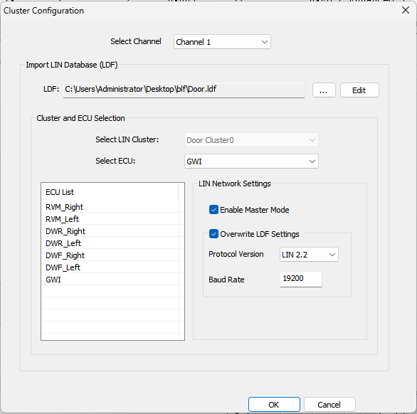
Section titled “3.2 Load the LDF”Open LIN Configuration and complete these steps:
- Select the Channel to associate with the database.
- Load the LDF. This example uses
Door.LDF. - In
Select ECU, select the node represented by the analyzer. - For master scheduling, select the Master node defined by the LDF and enable
Enable Master Mode. - Verify Protocol Version and Baud Rate.
- Enable
Overwrite LDF Settingsonly when the LDF parameters must intentionally be overridden.
The selected local ECU is important because BUSMASTER uses the Publisher in the LDF to determine each scheduled frame direction:
- If the Publisher is the selected Master ECU, the operation is Master Write.
- If the Publisher is another Slave ECU, the operation is Master Read.
3.3 Enable Interpret in Message Window
Section titled “3.3 Enable Interpret in Message Window”After loading the LDF:
- Locate
Message Windowon the LIN toolbar. - Open the arrow menu next to the Message Window button.
- Enable
Interpret. - Return to Message Window and select the
+beside a frame to expand its signals.
BUSMASTER then displays the frame name, signal names, raw values, and physical values instead of only hexadecimal bytes such as D9 or FF. This signal-level view is useful when testing doors, lamps, sensors, actuators, and similar functions.
3.4 Monitor selected signals with Signal Watch
Section titled “3.4 Monitor selected signals with Signal Watch”Message Window is suited to the complete message stream. When only a few values matter, add them to Signal Watch. BUSMASTER continuously updates their Physical Value and Raw Value across multiple frames, so the engineer can focus on test-relevant signals without repeatedly searching a scrolling message list.
4. Record and import LIN logs
Section titled “4. Record and import LIN logs”Field investigations often require more than observing current traffic. Engineers may need to record continuously, preserve evidence, share data with another team, or return to the time at which a problem occurred.
BUSMASTER LIN Logging supports:
LOG: the native BUSMASTER log format.ASC: a text format defined by Vector, suitable for interchange and direct inspection.BLF: a binary format defined by Vector, better suited to high bus load and long recordings.
These formats support storage, exchange, archiving, later analysis, and cross-team troubleshooting.
4.1 Configure and start logging
Section titled “4.1 Configure and start logging”- Select
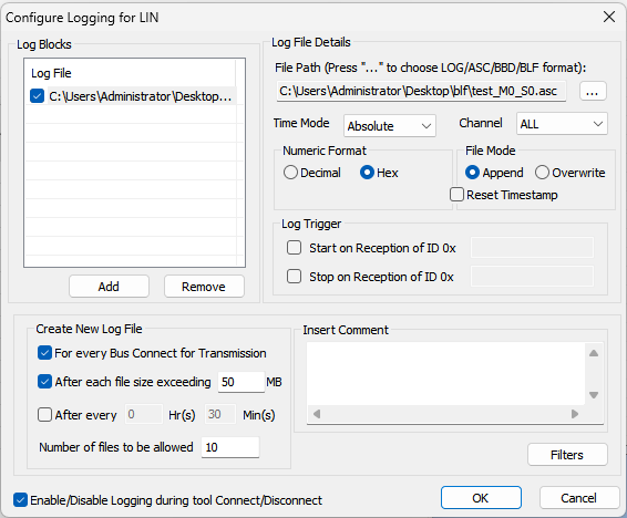
Loggingon the LIN ribbon to openConfigure Logging for LIN. - Add a logging configuration and select the destination and LOG, ASC, or BLF format.
- Set
Time Mode,Channel, Hex or Decimal, and Append or Overwrite. - For long runs, configure file-size rotation and a maximum file count.
- Consider starting and stopping logging automatically with Connect and Disconnect.
- Connect and acquire traffic. Disconnect normally at the end so the log is closed completely.
For long tests, BLF with automatic file rotation is recommended. Its compact representation and bounded file sizes simplify copying, archiving, and re-import.
4.2 Import a log into BUSMASTER
Section titled “4.2 Import a log into BUSMASTER”- Disconnect from the bus.
- Select
View -> Import, or drag the log file into Message Window. - Wait for loading to complete.
- Inspect timestamps, Tx/Rx, identifiers, payloads, and checksums.
- If the corresponding LDF is loaded, continue to view frame names and decoded signals.
- Use filters, Interpret, and Signal Watch to narrow the analysis.
LIN and CAN use a similar Logging workflow. For additional details about triggered recording, file rotation, import, and replay, see Logging, import, and replay formats.
5. Understand the four Transmit Window operations
Section titled “5. Understand the four Transmit Window operations”After confirming the receive path, configure transmit or response tasks in Transmit Window.
Without an LDF, enter the identifier, DLC, and payload directly. With an LDF, select a database frame and edit its signals; BUSMASTER encodes the payload.
5.1 Master Write
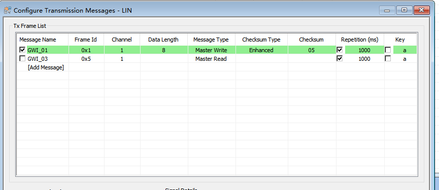
Section titled “5.1 Master Write”Master Write sends the complete Header and Payload. Configure Frame ID, Channel, Data Length, Data, Checksum, and the trigger method. Use it when the Master must write a control value or configuration to a Slave.
5.2 Master Read
Section titled “5.2 Master Read”Master Read sends the Header and waits for the target Slave to return the Payload. The matching Slave must respond within the required timing window or BUSMASTER reports a timeout.
For a Master Read timeout, check:
- whether the Slave is online;
- whether the requested identifier matches its response table;
- whether the required Slave Write entry is enabled; and
- whether bitrate, DLC, and Checksum mode match.
5.3 Sync Break
Section titled “5.3 Sync Break”The request portion of Sync Break and Master Read produces the same bus waveform. Their expected response is the opposite:
- Master Read expects a Slave response, so no response is a timeout.
- Sync Break expects no Slave payload, so an unexpected response is a receive error.
The operation type therefore cannot be determined only by observing that a request waveform was sent; the response expectation also matters.
5.4 Slave Write response table
Section titled “5.4 Slave Write response table”A Slave does not decide when to transmit. It waits for the Master to send a Header for an identifier and then returns its Payload within the specified timing.
In Slave mode, enabled Slave Write entries in Transmit Window form the local response table. Each entry defines:
- the identifier to which it responds;
- the response length;
- the Payload; and
- the Checksum type.
When a Master request matches an identifier, the hardware responds in real time with the predefined payload. The user does not have to see the request and click a transmit button. If the response table has no matching identifier, BUSMASTER does not return a payload for that Slave.
| Scenario | Local role | Active or passive | BUSMASTER location | Bus behavior |
|---|---|---|---|---|
| Bus monitoring | Master or Slave | Passive | Message Window | Captures existing requests and responses |
| Master Write | Master | Active | Transmit Window / Schedule | Master sends Header and Payload |
| Master Read | Master | Active | Transmit Window / Schedule | Master sends Header; Slave returns Payload |
| Sync Break | Master | Active | Transmit Window | Sends the synchronization interval and expects no Slave Payload |
| Slave Write | Slave | Passive | Transmit Window response table | Returns a Payload after a matching Header |
| Slave Read | Slave | Passive receive | Message Window | Receives the Payload written by the Master |
6. Run a complete communication plan with a master schedule
Section titled “6. Run a complete communication plan with a master schedule”Manual messaging is useful for validating one identifier. When a Master must poll several Slaves in a fixed order and at fixed intervals, configuring identifiers and Repetition values one by one is laborious and can drift from the LDF communication plan.
BUSMASTER reads a Schedule Table directly from the LDF. The user operates on a complete table instead of building independent periodic tasks. The analyzer and software can therefore turn database node roles, frame directions, ordering, and timing into a hardware schedule.
The behavior described here applies to the BUSMUST-maintained BUSMASTER 3.2.2.42. The original LIN Schedule Table Configuration help remains useful for basic LDF import and table/frame selection, but it does not cover the Transmit reconciliation, batch row creation, direction correction, and confirmed table-switch workflow added in 3.2.2.42 and described below.
6.1 Prerequisites
Section titled “6.1 Prerequisites”Confirm all three conditions:
- The Channel has an LDF containing a Schedule Table.
- The Channel is in Master mode.
Select ECUidentifies the Master node in the LDF.
A Slave does not run a local schedule. Its automatic behavior is defined by the Transmit Window response table described in section 5.4.
6.2 Select a table to run
Section titled “6.2 Select a table to run”Open Schedule Configuration and inspect the tables for the Channel. Expanding a table shows its Frame, ID, Type, Delay, and the enabled state of each frame slot.
Select the target table, for example by switching from Table0 to Table1. You do not need to create every Master Write and Master Read entry manually in advance.
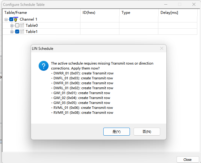
If required Transmit entries are missing, or an existing entry direction disagrees with the LDF Publisher, BUSMASTER displays one reconciliation prompt:
The active schedule requires missing Transmit rows or direction corrections. Apply them now?
The prompt lists every frame to create or correct. After confirmation, BUSMASTER:
- creates missing Transmit entries;
- creates Master Write when the Publisher is the selected Master;
- creates Master Read when the Publisher is a Slave;
- corrects an existing entry whose direction conflicts with the LDF; and
- marks the trigger source with the table name, such as
Trig by Table1.
Canceling the prompt does not apply the proposed modifications or the requested table switch; the previous schedule state remains unchanged.
6.3 Frame direction and Delay
Section titled “6.3 Frame direction and Delay”For an unconditional LIN frame:
- Publisher is the selected Master ECU: Master Write.
- Publisher is another Slave ECU: Master Read.
A schedule can therefore contain both operations while preserving the frame order defined by the LDF.
Delay [ms] is the time from the start of the current frame slot to the start of the next frame slot. It is not a wait inserted before the current frame.
BUSMASTER 3.2.2.42 basic scheduling supports LDF Unconditional Frames and explicitly selected diagnostic 0x3C Master Write and 0x3D Master Read frames. Event-triggered Frames, Sporadic Frames, Collision Resolving Schedules, automatic execution of configuration commands, and diagnostic transport-layer table insertion or switching are outside this basic scheduling scope and must not be guessed as ordinary Master Read or Master Write operations.
6.4 Run the table in hardware
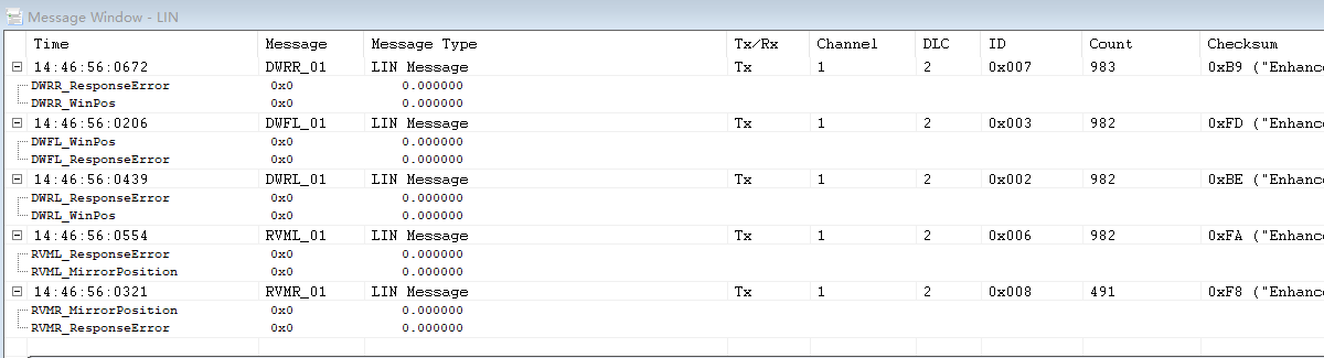
Section titled “6.4 Run the table in hardware”Select Connect after configuration. BUSMASTER converts the active schedule into one complete hardware task and executes its frame order and Delay values repeatedly. A table may mix Master Write, Master Read, and different intervals without requiring manual transmit actions.
Schedule Configuration supports both whole-table and per-frame enable controls. Enabling the Table1 row enables the table and, by default, all of its frames. Expand the table to clear or restore individual slots. A disabled slot is simply not transmitted; its position on the original LDF timeline remains reserved, so later frames do not move earlier.
During execution:
- Message Window shows the enabled identifiers repeating in order.
- A frame can be enabled or disabled from Schedule Configuration or its corresponding Transmit Window row.
- After a Master Write signal value is changed, subsequent schedule iterations use the updated payload.
- A scheduled Transmit row shows
Trig by {table name}in Repetition and is controlled by schedule timing rather than ad hoc single-transmit actions.
Independent periodic Master tasks that are enabled in Transmit Window but do not belong to the current table can remain active as supplemental tasks and are merged after the scheduled work.
6.5 Switch between tables
Section titled “6.5 Switch between tables”When an LDF defines multiple communication or diagnostic tables, select another table to switch. BUSMASTER reconciles its required Transmit rows again. The switch takes effect only after the changes are confirmed and applied successfully. There is no need to delete old tasks and rebuild the new table row by row.
6.6 Do not confuse the three task tables
Section titled “6.6 Do not confuse the three task tables”| Type | Role | Location | Configuration | Purpose |
|---|---|---|---|---|
| Master schedule | Master | Schedule Configuration | Comes from the LDF; select the table and enabled frames | Runs Master Write and Master Read in LDF order and timing |
| Master task list | Master | Transmit Window | Add Master Write, Master Read, or Sync Break manually | Single, periodic, or supplemental tasks outside the schedule |
| Slave response table | Slave | Transmit Window | Add Slave Write entries manually | Hardware returns a Payload after a matching Master request |
In short: Schedule Configuration defines the order and period in which the Master reads and writes; Transmit Window in Master mode adds independent transmit tasks; Transmit Window in Slave mode defines what the analyzer returns when the Master reads.
7. Troubleshooting
Section titled “7. Troubleshooting”7.1 The device is not found
Section titled “7.1 The device is not found”Check, in order:
- USB connection.
- Device presence in Windows Device Manager.
- Correct Windows driver installation.
BUSMUST USB-LINin Driver Selection.- Physical-channel detection and mapping in Channel Configuration.
7.2 Message Window shows no traffic
Section titled “7.2 Message Window shows no traffic”- Check LIN and GND wiring.
- Check that the bus has a suitable 12 V supply.
- Match 12V Output to the actual supply arrangement.
- Check Baudrate.
- Check whether Advanced settings exclude the target identifier.
- Receive all IDs during initial troubleshooting.
- For monitoring only, try Slave mode automatic bitrate detection.
7.3 Master Read times out
Section titled “7.3 Master Read times out”- Confirm that the Slave is online.
- Match the Master request identifier to the Slave response table.
- Enable the corresponding Slave Write entry.
- Check DLC, Checksum, and bitrate.
Master Read sends only the Header. The Master does not generate a Payload when no Slave responds.
7.4 Slave Write appears not to transmit
Section titled “7.4 Slave Write appears not to transmit”Slave Write is not an active transmit-on-demand operation. The hardware returns its predefined Payload only after a Master requests the same identifier.
If the message must be sent actively like a periodic task, verify whether the analyzer should instead use Master mode and Master Write.
7.5 Selecting a schedule displays a create or correct prompt
Section titled “7.5 Selecting a schedule displays a create or correct prompt”This is the normal BUSMASTER 3.2.2.42 reconciliation workflow. BUSMASTER checks whether the target table’s Master Write and Master Read entries exist and whether each direction matches the LDF Publisher. Review the list and confirm to create missing rows and correct directions in one operation. Cancel if the current Transmit template must remain unchanged, then correct the LDF or existing entries before trying again.
7.6 The schedule cannot be activated
Section titled “7.6 The schedule cannot be activated”- Confirm that the Channel is Master.
- Confirm that the LDF is loaded on the correct Channel.
- Select the LDF Master node in
Select ECU. - Confirm that the LDF contains the target Schedule Table.
- Enable the target table and the required frame slots.
8. Summary
Section titled “8. Summary”BUSMASTER and a BUSMUST LIN analyzer support a complete LIN workflow: monitor and exchange raw identifier-based messages, load an LDF to decode frames and signals, configure Master tasks and Slave responses, and run an LDF-defined master schedule in hardware. Signal Watch and LOG, ASC, or BLF recording and import keep signal analysis and problem history in the same tool, supporting development debugging, bench validation, and long-duration testing.
Primary resources
Section titled “Primary resources”- BUSMUST WeChat article: LIN messaging and schedule tables
- BUSMASTER tutorial collection
- Download current or archived BUSMASTER releases
Source: BUSMUST technical knowledge base busmaster-classic-lin-send-receive-schedule.md. This public guide is maintained by the website content pipeline. Use the download center for current and archived software releases.
Illustrated LIN workflow
Section titled “Illustrated LIN workflow”These original screenshots come from the BUSMASTER manual or illustrated guide and show the actual workflow.