
Getting Started
If you are using BUSMASTER application for the first time then the following section will help you to get familiarized with the features of this tool. For this we will operate the BUSMASTER in self-reception mode i.e. the BUSMASTER tool will be the sender and receiver of CAN or CAN FD messages.
Initial Setup
- Call BUSMASTER.exe by double clicking the appropriate icon in the BUSMASTER program group.
- The tool will only work with Active mode. Make sure that the USB hardware is connected to the PC and CAN or CAN FD bus.
- For setting the baud rate, select the CAN driver and open Channel Configuration. For BUSMUST CAN FD hardware, configure the nominal baud rate, CAN FD data baud rate, sample point, terminal resistor, and CAN/CAN FD mode before connecting. Other than the baud rate values this dialog can be used to set other parameters like sampling point, synchronization jump width, hardware acceptance filter, and controller-specific options.
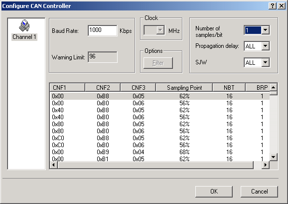 In USB interface, setting Warning limit is not supported. The default warning limit value 96 is set internally and user cannot change this value. Dual filtering is not supported in USB interface. Only single filtering is supported.
 - To send CAN or CAN FD messages, the messages must be defined first. Select CAN –> Transmit Window. A dialog as shown below pops up.
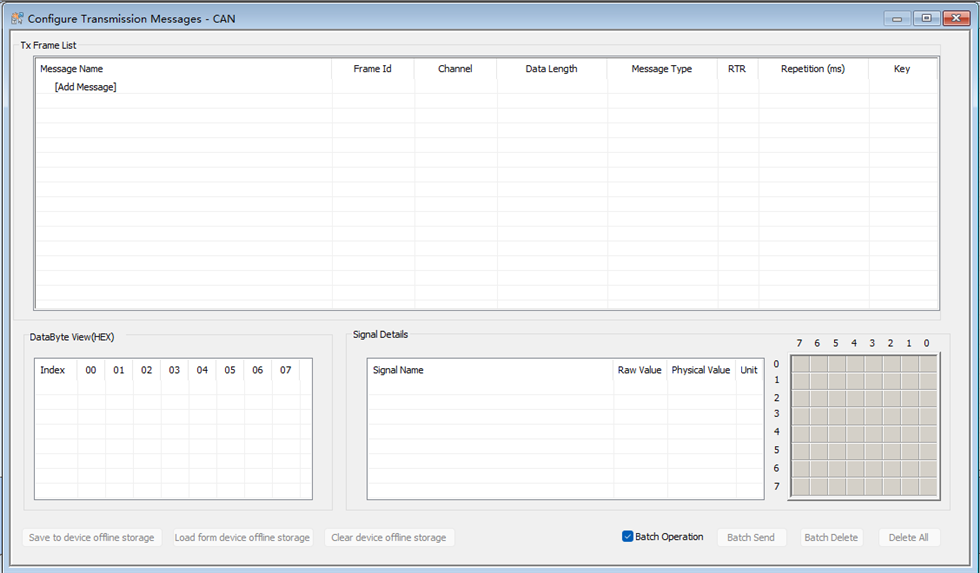
- You can add a total of 32 Message Blocks having trigger condition either as “On Key” or “On Time” or both. Each block of message can have a total of 64 messages.
- You can activate any message block selectively for transmission by selecting a check box in Message Blocks list.
Message can be added that are not in the database as well as in the database. For details about this refer Transmit Message(s)
From the same dialog box one can select the time interval between two consecutive messages by entering the delay value in milliseconds in the Interval box. The Key box is used to enter key value for key trigger. The transmission can be configured as one shot or cyclic by selecting or deselecting the item Monoshot.
Close the dialog by clicking on OK button. You can use Apply button to save the changes without closing the dialog.
User can also select the message from the list and transmit over the CAN or CAN FD bus by using Send button or by right click in the list and selecting the Send menu. Message blocks and messages in blocks can be added/deleted by selecting the menus. The pop up menu is displayed when user right clicks the corresponding list.
The message details can be modified even the transmission is in progress. Message data can be directly modified by changing the data byte values or the signal values. Signal values can be given as raw value or physical value. In all these cases all other values will be updated accordingly. You can modify the message details and select Apply or OK button to reflect the changes for transmission. During transmission you can’t modify the details of message block which is active. But you can add a new block or change the message block details for block, which is not active.
On selection of start transmission only those blocks which is active having at least one message frame will be transmitted. Also if the trigger is selected as On Key then the transmission will start when the corresponding key is pressed.
Now the messages to be transmitted have been configured and it’s ready to be transmitted. Select the Connect menu from the CAN menu option. This initializes the CAN controller. To initiate the transmission of the messages go to the menu CAN**–> Transmit –> Enable**.
A cross mark on the message icon in the Tx Message list indicates that the message is not available in the database.
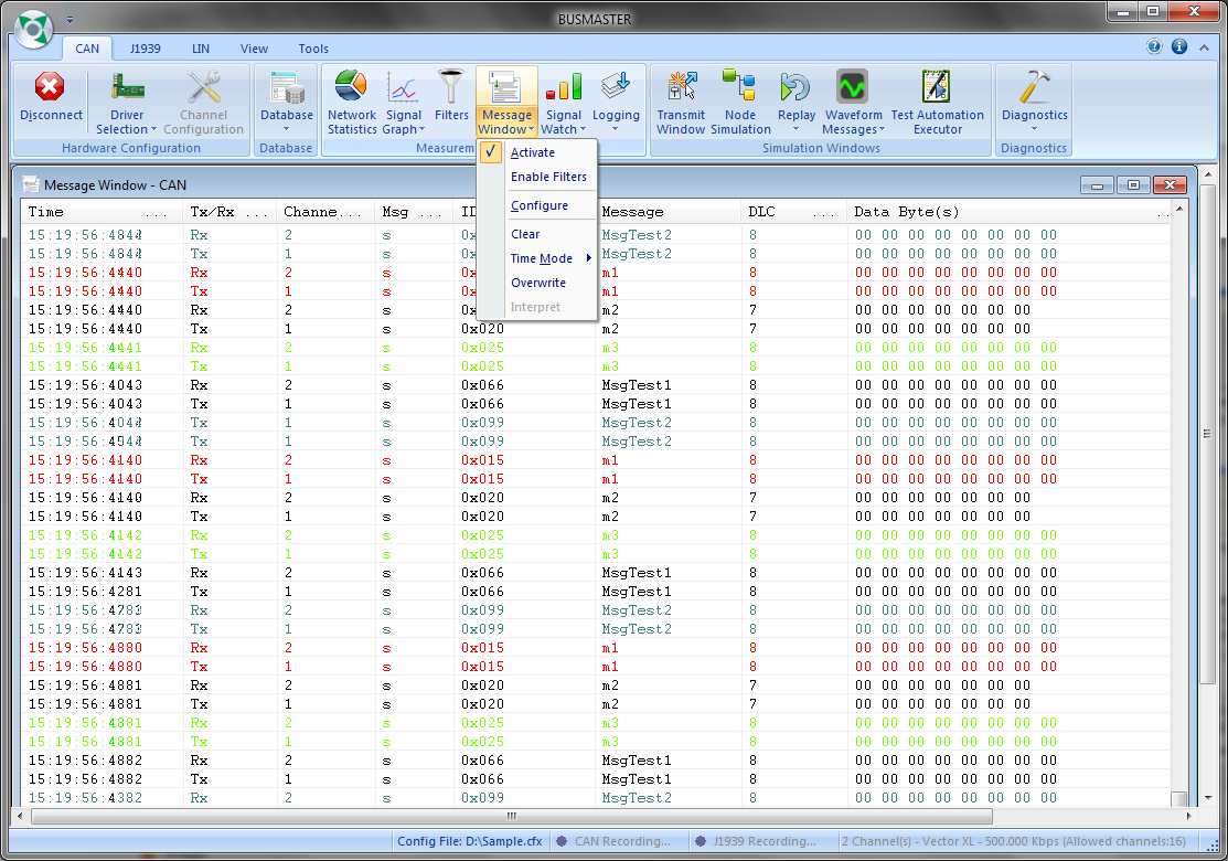
If the installation is proper and working then you should be able to see the configured messages being transmitted and receive simultaneously in the Message display window as shown in below
Authoritative source: BUSMASTER DITA help source getting_started.dita, compiled into BUSMASTER.CHM with the application.