BUSMASTER basic transmit and receive
This guide covers the standard BUSMUST BUSMASTER workflow: selecting a device, mapping channels, configuring CAN or CAN FD timing, receiving and filtering messages, transmitting frames, decoding DBC signals, monitoring statistics, plotting signals, and troubleshooting common communication problems.
The full illustrated Chinese article is also available from the BUSMUST WeChat account: BUSMASTER basic transmit and receive.
BUSMASTER is a CAN and LIN analysis application for monitoring and transmitting bus messages, database decoding, statistics, logging, and replay. The BUSMUST-maintained edition adds CAN FD, a UDS panel, ASC and BLF support, and device-specific features.
Download, install, and start
Section titled “Download, install, and start”Download the current BUSMASTER installer from the BUSMUST download center. The same page provides archived versions when a project must remain on an earlier release.
Complete the installation wizard on Windows 10 or Windows 11. If Windows rejects the device-driver INF file, follow the driver package instructions; some legacy driver packages may require driver-signature enforcement to be disabled temporarily.
If Windows does not recognize a connected device, verify the driver installation and check that the device appears in Device Manager. Start BUSMASTER and switch to the CAN ribbon after the device is recognized.
Select the driver and map hardware channels
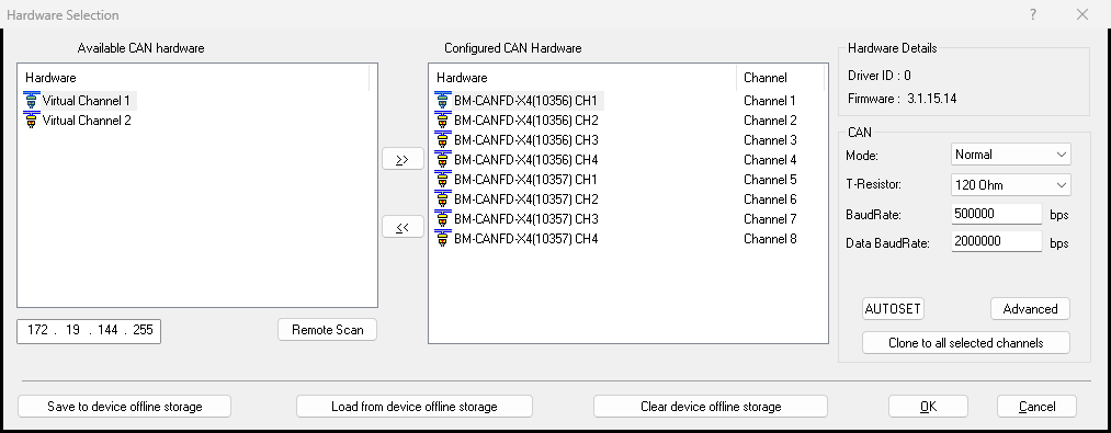
Section titled “Select the driver and map hardware channels”Open CAN -> Driver Selection and select BUSMUST USB-CAN(FD).
Then map each physical interface channel to a BUSMASTER logical channel:
- Hardware channel: a physical port such as channel 1, 2, or 3 on a specific interface.
- BUSMASTER logical channel:
Channel 1,Channel 2, or another channel used by the application.
BUSMASTER can use a port only after this mapping is complete. For a controlled loop test, multiple physical ports may be connected to the same test bus so one port transmits and the others receive. When connecting to a real ECU, map and wire the physical channel required by the installation.
Configure channel parameters
Section titled “Configure channel parameters”The parameters used most often are:
Mode: normallyNormal.T-Resistor: controls the device-side 120-ohm terminator.BaudRate: arbitration or nominal bitrate, also used by classic CAN.Data BaudRate: CAN FD data-phase bitrate.
Operating modes
Section titled “Operating modes”Normal: transmits and receives on a real network or multi-channel loop setup.Loopback: verifies the local software transmit path and basic channel operation without an external bus.Listen Only: monitors an existing network without actively transmitting acknowledgements.
Termination
Section titled “Termination”A CAN bus normally has one 120-ohm terminator at each physical end. Missing or incorrect termination can make communication intermittent or prevent it entirely. During initial bring-up, confirm that suitable termination is present; then adjust the device-side resistor to match the actual topology.
CAN FD bitrates
Section titled “CAN FD bitrates”CAN FD normally uses two bitrates:
BaudRatefor the arbitration phase.Data BaudRatefor the data phase.
If classic CAN traffic works but CAN FD does not, verify both rates against the other node. Advanced settings expose the sample point; the recommended default is commonly 80% unless the network design specifies otherwise.
BUSMASTER 3.2.2.40 has two known UI limitations: selecting another SJW value does not take effect through this dialog, although BMAPI SDK configuration does; and the data-segment setting in this interface cannot be configured independently from the arbitration-segment value. These notes are release-specific, so consult the current changelog when using a later version.
Select Connect after checking all channel parameters.
Receive messages in Message Window
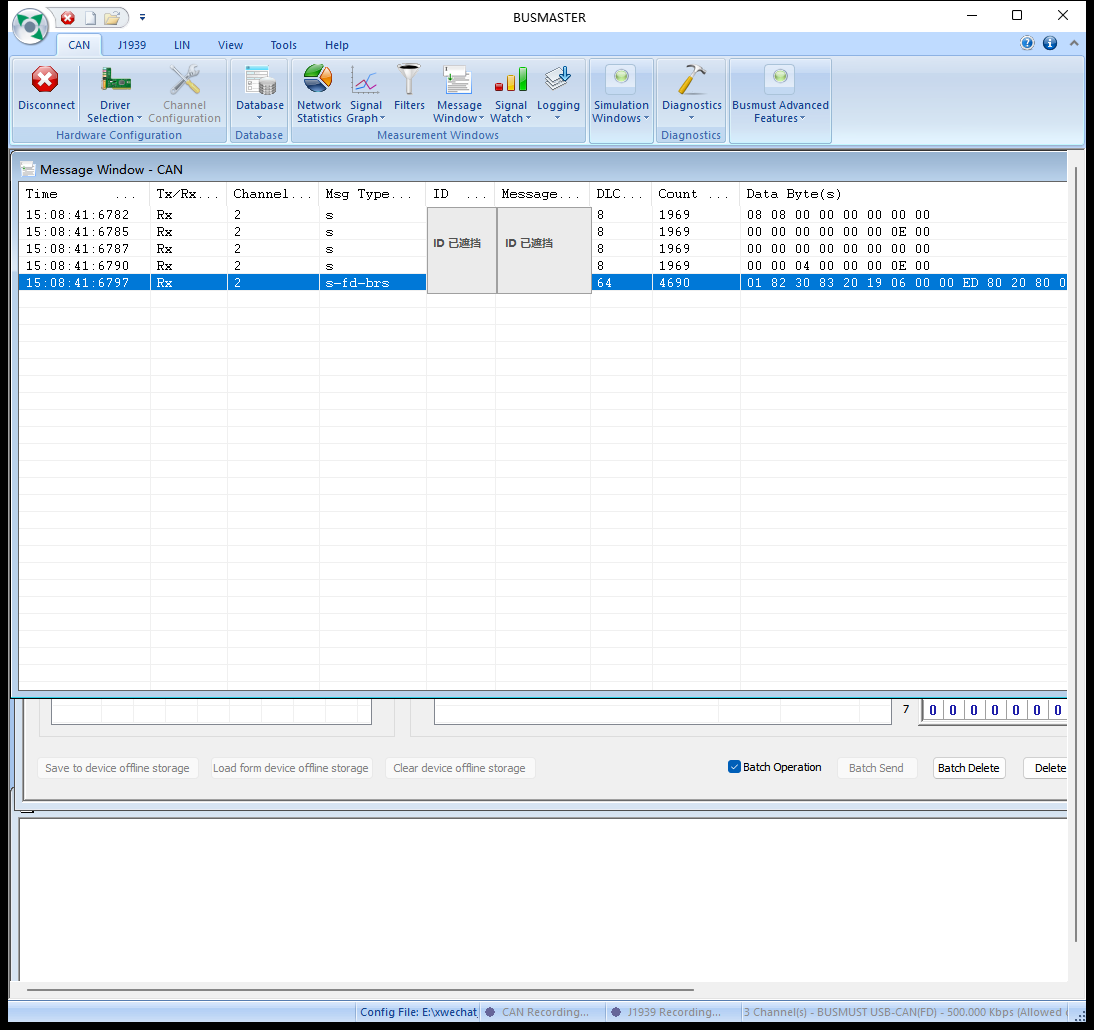
Section titled “Receive messages in Message Window”When the bus is connected and active, Message Window shows traffic with fields such as:
Channel: BUSMASTER logical channel.Rx/Tx: direction.ID: CAN identifier.DLCandData Byte(s): data length and payload.Time: timestamp.Count: accumulated instances of the message.
Useful display options include:
Overwrite: keeps one row per identifier and updates its latest value.Append: adds messages in time order.Auto scroll: follows the newest appended message.Time Mode: changes timestamp presentation.- Buffer and refresh options: control display history and update behavior.
Interpret: expands payload bytes into DBC signal values after a database is loaded and associated.
Time can be shown as the interval between adjacent messages (Relative), elapsed time since connection (Absolute), or system date and time for alignment with external logs.
Configure a software receive filter
Section titled “Configure a software receive filter”A BUSMASTER software filter controls what modules such as Message Window display. Creating a filter does not enable it automatically. The complete workflow has three steps.
1. Create the filter
Section titled “1. Create the filter”Open CAN -> Filters and create either:
- a
passfilter, which allows matching messages; or - a
stopfilter, which suppresses matching messages.
Filter Attributes can match ID or ID Range, ID Type, Frame Type, Direction, and Channel. Select Add to add the condition to the filter.
2. Assign the filter to Message Window
Section titled “2. Assign the filter to Message Window”Open Configure Message Display - CAN, enter the filter configuration, and move the new filter into Selected Filters in the Filter Selection Dialog.
3. Enable filtering
Section titled “3. Enable filtering”Select Enable Filters from the Message Window menu.
The effective sequence is therefore: create the filter, assign it to Selected Filters, and enable filters. If a configured filter appears ineffective, verify all three steps.
Transmit messages manually
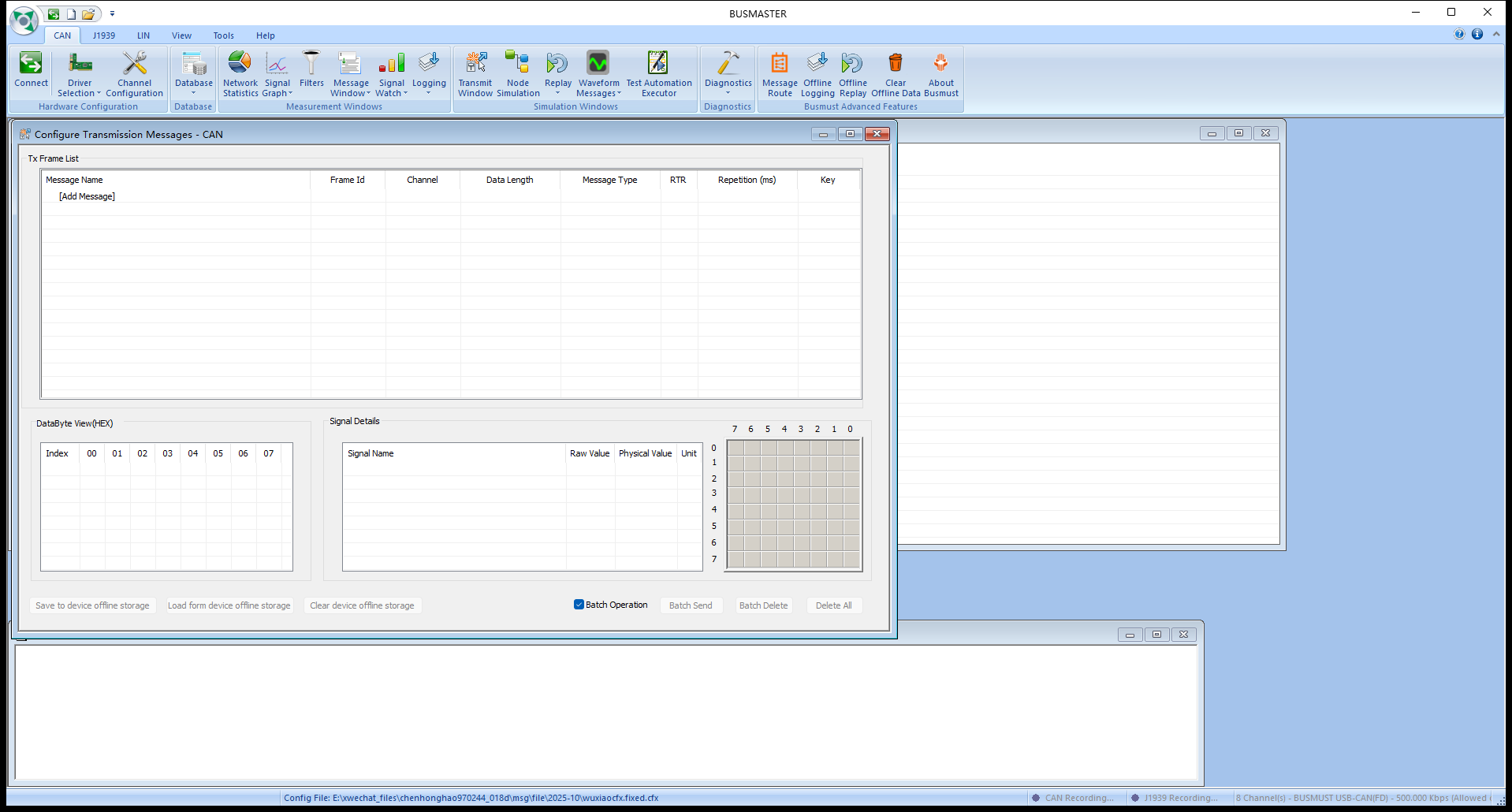
Section titled “Transmit messages manually”Open CAN -> Transmit Window. Double-click [Add Message] in the Message Name column to create a transmit entry.
- With a DBC loaded, select a database message from the list.
- Without a DBC, type an identifier such as
0x135or0x789.
Then configure:
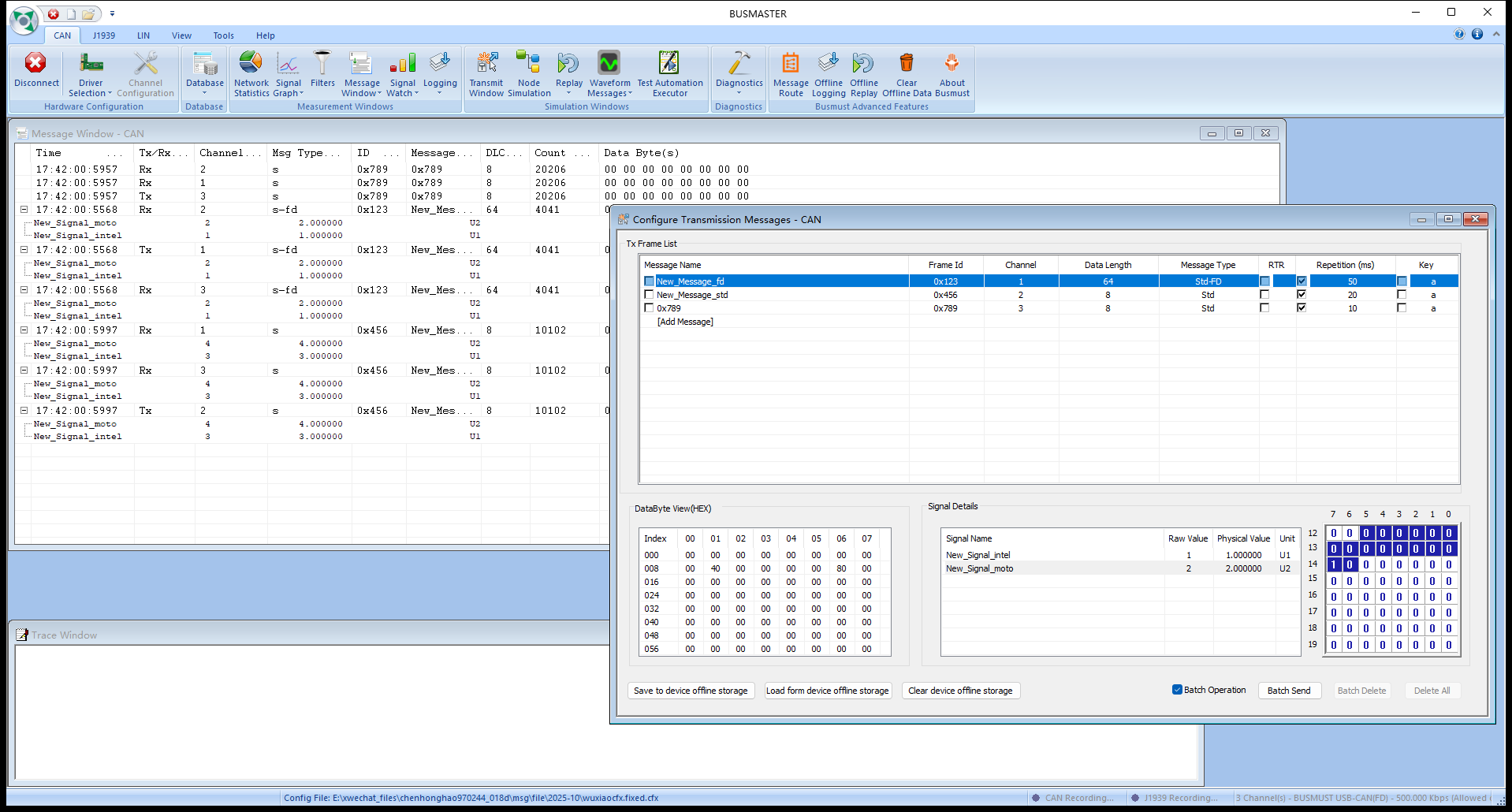
Frame Id: identifier.Channel: BUSMASTER logical transmit channel.Data Length: payload length.Message Type: classic CAN, CAN FD, or CAN FD+BRS, subject to device capability.RTR: remote-frame option for classic CAN.Repetition (ms): periodic transmit interval.Key: keyboard trigger.
Transmit once for an initial check, or enable periodic transmission after the channel and frame format are confirmed.
Load a DBC and work with signals
Section titled “Load a DBC and work with signals”A DBC is not required to transmit or receive raw frames. It provides message names, signal definitions, and physical-value conversion.
Import the DBC and associate it with the current CAN network. BUSMASTER may close the association dialog without a separate success notification. Verify the result by checking that messages or signals are available in Transmit Window, Signal Watch, Signal Graph, or Message Window.
Common signal views are:
Message Window + Interpret: expands messages into Raw Value, Physical Value, and Unit.Signal Watch: monitors selected signals continuously.Signal Graph: plots selected signals over time.
After enabling Interpret, messages defined in the DBC display their names and signals. An identifier not present in the DBC remains visible as raw traffic but cannot be expanded into signals. The database affects presentation and signal editing, not whether the raw frame can be transmitted or received.
When a DBC message is selected in Transmit Window, DataByte View(HEX), Signal Details, and the bit layout show the payload. Double-click a signal’s Raw Value or Physical Value to edit it; BUSMASTER updates the data bytes according to the DBC definition.
Use Network Statistics
Section titled “Use Network Statistics”Network Statistics provides a quick channel-level health check:
- Rx and Tx counts per channel.
- Current message rate.
- Approximate bus load and unexpected load changes.
Use it alongside Message Window when determining whether traffic is present or whether a transmitted request produces activity.
Plot signals with Signal Graph
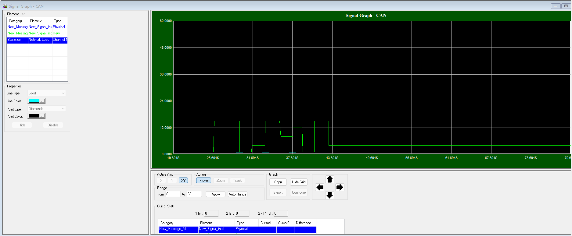
Section titled “Plot signals with Signal Graph”Load and associate a DBC before using Signal Graph. Open the graph, select database messages and signals in its configuration, connect to the bus, and observe the curves as decoded values change. Signal Graph is a visualization layer and does not alter bus traffic.
Troubleshooting
Section titled “Troubleshooting”The device or channel is missing
Section titled “The device or channel is missing”- Check the USB connection, device power, and indicators.
- Confirm that Windows Device Manager lists the BUSMUST device.
- Resolve any yellow warning icon by reinstalling the correct driver package.
- Make sure another application is not using the device.
- Return to Driver Selection and select
BUSMUST USB-CAN(FD).
Channel mapping and bus configuration can begin only after Windows and the driver recognize the device.
Messages are not received, or the other node receives nothing
Section titled “Messages are not received, or the other node receives nothing”Check the physical layer and channel first:
- CANH and CANL wiring and ground reference.
- Physical-to-logical channel mapping.
- Matching arbitration bitrate at both ends.
- Matching CAN FD data bitrate and BRS configuration.
- Suitable termination.
- Power and operating state of the other node.
Then check Transmit Window:
- Correct
ChannelandFrame Id. - Matching standard or extended identifier type.
- Correct classic CAN, CAN FD, or CAN FD+BRS
Message Type. - Valid DLC and data length.
- Periodic transmission enabled or a manual transmit action performed.
- BUSMASTER is connected.
Finally, disable or review software and hardware filters. Confirm that the software filter is selected and intentionally enabled, and restore a device-side hardware filter to Accept All while diagnosing the receive path.
Communication works but is unstable
Section titled “Communication works but is unstable”Verify arbitration and data bitrates, BRS, sample point, termination, cable length and quality, shielding, grounding, and topology. For an MCU-based CAN FD peer, also verify transmitter delay compensation (TDC). Rising error counts, intermittent loss, or BusOff generally indicate a timing or physical-layer issue rather than a simple display problem.
After BusOff, disconnect, correct the underlying configuration or wiring, and reconnect. Do not rely on repeated reconnection without resolving the cause. CAN FD problems can appear only in the faster data phase even when arbitration looks healthy.
Further reading
Section titled “Further reading”- BUSMUST WeChat article: BUSMASTER basic transmit and receive
Source: BUSMUST technical knowledge base busmaster-basic-send-receive.md. This public guide is maintained by the website content pipeline. Use the download center for current and archived software releases.
Illustrated BUSMASTER workflow
Section titled “Illustrated BUSMASTER workflow”These original screenshots come from the BUSMASTER manual or illustrated guide and show the actual workflow.