
Diagnostics Settings
Diagnostics settings window is used to set the transport, addressing, timing, CAN FD, tester-present, and seed/key algorithm settings for diagnostic request and response messages.
To configure diagnostic settings use CAN->Diagnostics->Settings. This will display the window as shown below.
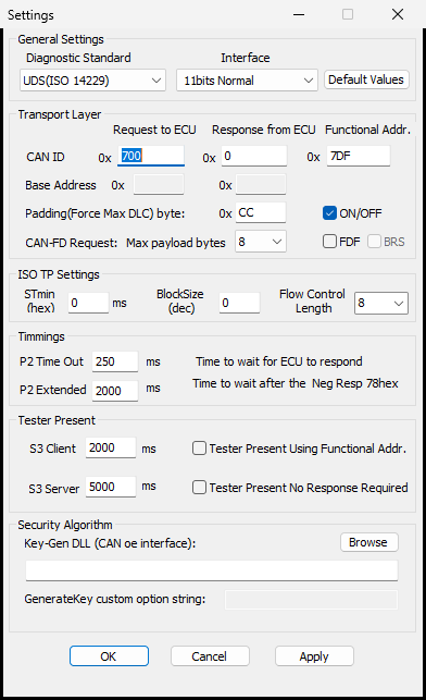
Diagnostics Standard To select diagnostics standard, such as UDS (ISO 14229) or ISO 14230 where supported. Interface To select the addressing interface, such as 11 bits normal, 11 bits extended, or 29 bits interface where supported. Default Values Restores the diagnostic settings to default values. CAN ID (Request to ECU) To set the identifier of the diagnostic request message that is to be transmitted CAN ID (Response from ECU) To set the identifier of the diagnostic response message that is to be received Functional Address Specifies the functional request identifier used when functional addressing is enabled. Base Address Indicates the base of the 11 bit message identifier. It is enabled only if the selected interface requires a base address. Padding (Force Max DLC) Byte Specifies the padding byte used when the transmitted diagnostic frame must be padded to the selected maximum payload length. Padding is commonly set to values such as 0xCC or 0x00 depending on the ECU requirement. Padding ON/OFF Enables or disables forced padding for diagnostic request frames. CAN-FD Request When checked, diagnostic requests are sent as CAN FD frames. Configure the CAN channel as CAN FD before connecting, and confirm that the ECU supports diagnostics over CAN FD. Max Payload Bytes Selects the diagnostic request payload length used by the transport layer. For classic CAN this is normally 8 bytes. For CAN FD, select a value that matches the ECU and network requirement. FD and BRS FD enables CAN FD frame format for diagnostics. BRS enables bit-rate switching in the CAN FD data phase when supported by the ECU, channel configuration, and selected BUSMUST device. STmin Indicates the minimum time delay between two consecutive ISO-TP consecutive frames. Block Size Maximum number of consecutive frames that a sender can send before waiting for flow control. Flow Control Length Length of the flow control frame to be transmitted. P2 Time Out Indicates the time that the tool should wait for the ECU to respond. P2 Extended Indicates the extended wait time after a negative response such as response pending is received. S3 Client Indicates the time delay between tester-present messages transmitted by BUSMASTER. S3 Server Indicates the ECU-side session timeout reference. Set it according to the ECU diagnostic specification. Tester Present Using Functional Address Transmits tester-present messages using the configured functional address instead of the physical request ID. Tester Present No Response Required Uses the UDS suppress-positive-response behavior for tester-present requests when the ECU supports it. Key-Gen DLL Selects the key-generation DLL used by Security Access. The DLL should implement the expected CANoe-compatible key generation entry point when the ECU requires seed/key unlock. GenerateKey Custom Option String Optional string passed to the key-generation DLL. Use this only when the DLL or ECU project requires additional parameters.
For UDS on CAN FD, confirm the request ID, response ID, addressing type, STmin, block size, P2, and P2 extended values with the ECU supplier. Incorrect transport settings usually appear as no response, timeout, or incomplete multi-frame transfer.
Authoritative source: BUSMASTER DITA help source Diagnostics_Settings.dita, compiled into BUSMASTER.CHM with the application.