
J1939
Introduction
Section titled “Introduction”J1939 is a CAN-based layer 7 protocol mainly used in Truck and Bus control and communications. The typical properties of J1939 are:
- 29 bit extended CAN identifier.
- Point-to-point and broadcast communication.
- Transmission up to 1785 bytes.
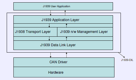
J1939 Protocol Stack
Parameter Group Number (PGN):
Section titled “Parameter Group Number (PGN):”PGN identifies the Parameter Group (PG). PGs point to information of parameter assignments within 8 byte CAN data field, repetition rate and priority. The structure of PGN allows a total of 8672 different Parameter Groups per page – 2 pages are available.
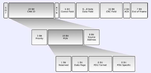
Parameter Group Number
Transport protocol function
Section titled “Transport protocol function”Transport protocol functions are mainly used for transmission and reception of multi-packet messages which can extend upto 1785 bytes. Function involves packaging into sequence of 8 byte size messages during transmission, re-assemble of such data at the receiver side.
1. Multi-packet broadcast
Section titled “1. Multi-packet broadcast”A broadcast message is broadcasted to all nodes in the network. Sender node must first send a Broadcast Announce Message (BAM) followed by sequence of 8 byte data. Receiving nodes can prepare for reception if interested.
BAM message contains following information.
-
PGN to be sent
-
Size of multi-packet message
-
Number of packages
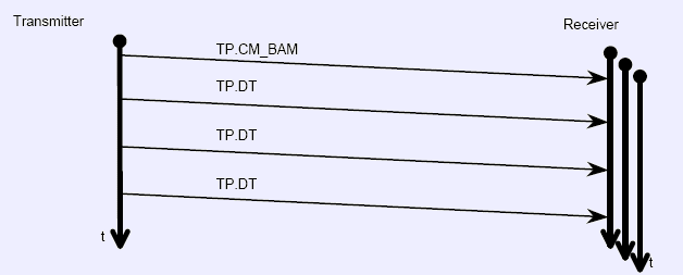
Multi-packet broadcast data transfer
2. Multi-packet peer-to-peer
Section titled “2. Multi-packet peer-to-peer”For destination specific data transmission, communication needs to be established hence subject to flow control. Transport protocol function is applied in three steps.
1. Connection Initialization - The sender of a message transmits a Request to Send message. The receiving node responds with either a Clear to Send message or a Connection abort message incase it decides not to establish connection.
2. Data Transfer - Sender transmits data after receiving Clear to Send message.
***3. Connection Closure -***The receiver of the message , upon reception sends End of Message ACK message.
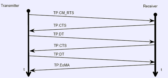
Multi-packet peer-to-peer data transfer
Network management
Section titled “Network management”Each ECU in a J1939 network must hold at least one NAME and claim one 8 bit address for identification purposes.
***1. ECU NAME -***64 bit identifier includes an indication of the ECU’s main function performed at the ECU’s address.

J1939 NAME Fields
***2. ECU Address -***8-bit ECU address defines the source or destination for messages.
Address claiming procedure
Section titled “Address claiming procedure”The address claim feature considers two possible scenarios
***1. Sending an address claimed message (ACL) -***At the network startup, an ECU will cliam an address and send Address Claimed message. All ECUs receiving the address claim will record and verify the newly claimed address with their internal address table. In case of an address conflict, the ECU with the lowest NAME will succeed.
***2. Request for Address Claimed message -***An ECU Requests ACL message from all nodes in the network and claims available address.### BUSMASTER.J1939
Initialisation
Section titled “Initialisation”Prerequisite of employing the J1939 functionalities is getting hold of J1939 interface, and this is the sole purpose of this function. This will query for the available J1939 interface. Once this is available, the associated menu item and button will be disabled. The query operation involves DIL.J1939 interface initialisation, a J1939 client registration and finally the J1939 logger interface query and initialisation. Outcome of the query operation can be seen on the Trace window.
Configure Logging
Section titled “Configure Logging”This invokes the logging configuration dialog box whose layout and the configuration procedure is exactly same as that of CAN. Only difference is that for J1939 a message is identified not by CAN identifier, but by its PGN number.
Start Network
Section titled “Start Network”This function connects the application to the J1939 network. Both the associated menu item and toolbar icon are toggling in nature and hence shuttle between “Go Online” and “Go Offline” modes.
Transmit Message
Section titled “Transmit Message”This brings in the J1939 transmit message window in which the presently transmittable message can be configured and sent in both monoshot and cylcic mode.
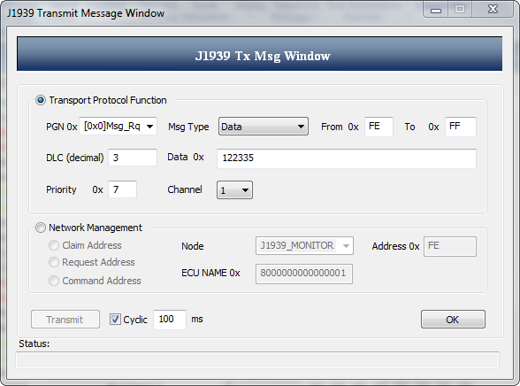
J1939 Transmit Message Window
Logging
Section titled “Logging”By selecting the associated menu item or clicking on the toolbar icon, the user can start the logging process. This has the characteristics of a toggle switch and hence using the same, ongoing logging process can be stopped too.
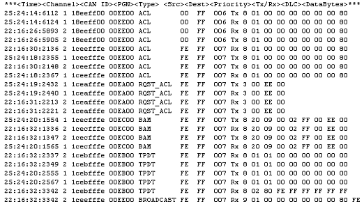
J1939 Log File
Message Database
Section titled “Message Database”1. Database Editor:
Section titled “1. Database Editor:”J1939 database editor is similar to CAN database editor. User can define a new message based on its PGN and it can have maximum data size of 1785 bytes.
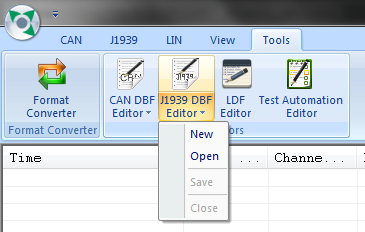
2. Database Function:
Section titled “2. Database Function:”User can associate/dissociate J1939 database files.
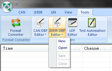
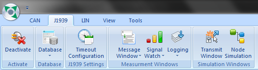
J1939 features can be accessed from the below options.
Configure Timeouts
Section titled “Configure Timeouts”User can configure timeouts which will be considered when flow control messages are being sent or received.
Corresponding dialog box can be invoked by clicking the menu J1939 –> Timeout Configuration.
Timeout’s description will appear on clicking the corresponding check box.
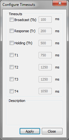
**Tb:**Time interval between two packets in broadcast transmission.
**Tr:**Maximum wait period for a sender to receive a response from the receiver.
**Th:**Time interval between two ‘Clear to Send’ message when delaying the data.
**T1:**Maximum wait period for a receiver when more packets were expected.
**T2:**Maximum wait period for a receiver to receive data packets after sending ‘Clear to Send’ message.
**T3:**Maximum wait period for a sender to receive ‘End of Message Acknowledgement’ after sending last data packet.
**T4:**Maximum wait period for a sender to receive another ‘Clear to Send’ message after receiving one to delay the data.
Signal Watch
Section titled “Signal Watch”J1939 signal watch window is similar to CAN signal watch window. User can add SPNs(Signals) of the PGN defined in database.
Node Programming
Section titled “Node Programming”Seperate menu items are available for configuring J1939 node programming. Use ‘J1939 –> Node Simulation –> Configure’ menu for configuring nodes. Most of the features of J1939 node programming remain same as that of CAN. Few differences are listed down.
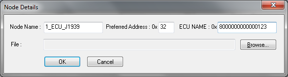
**1. Node Addition :**User has to provide following information to create a new node.
a. Node Name b. Preferred Address c. 64 bit ECU name.
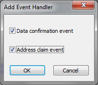
**2. Function Editor :**J1939 Function Editor is similar to CAN Function Editor. In addition to the handlers available in the CAN Function Editor it has Event Handlers where user can configure
- **Data confirmation event :**Handler is executed whenever a long(> 8 bytes) message is transmitted.
void OnEvent_DataConf(UINT32 unPGN, BYTE bySrc, BYTE byDest, BOOL bSuccess);
unPGN - PGN of the message transmitted. **bySrc -**Source node. **byDest -**Destination node. bSuccess - Result of transmission. ( TRUE-success, FALSE-failure)
- **Address confirmation event :**Handler is executed whenever a node claims or loses an address.
void OnEvent_AddressClaim(BYTE byAddress) ;
**byAddress -**New Address claimed by the node. Address lost If the value is 254.
Note: These event handlers are always enabled once added.
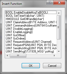
**3. J1939 API Reference :**A new set of API is introduced in-order to perform functions on J1939 bus. Please refer following section API Reference J1939 for further details.
Authoritative source: BUSMASTER DITA help source J1939.dita, compiled into BUSMASTER.CHM with the application.