
Modbus Integration: Add Standard Industrial I/O to an Automotive Bench
BMCLI brings standard Modbus acquisition and control modules into an automotive bench alongside CAN/CAN FD devices. Starting with module resource access, this article explores shared displays and cross-bus coordination using readily available industrial modules.
During battery-controller integration, CAN/CAN FD data may already be visible while the bench still lacks enclosure temperature, auxiliary voltage acquisition, and fan or test-load switching. Developing a separate CAN acquisition board for these auxiliary quantities may not be the easiest approach.
For a temperature input or low-voltage relay output, consider existing modules first. Industrial suppliers offer many temperature, analog-input, and relay modules using Modbus RTU/RS-485 or Modbus TCP. Finding suitable products through common procurement channels such as Taobao lets you focus on the system instead of designing circuits, firmware, and private protocols for an auxiliary measurement or switch. Reuse provides the cost advantage; verify range, isolation, accuracy, and quality against project requirements.
Connecting them to BMCLI lets industrial I/O and automotive buses share acquisition, displays, and automation. This is the purpose of Modbus support: bringing the existing module ecosystem into the laboratory, beyond merely adding another protocol name.
For example, the computer connects to controller CAN/CAN FD through a BUSMUST analyzer and to temperature/relay modules through a suitable RS-485 interface. One page displays ECU messages, temperature, voltage, and switch states. Standard modules handle appropriate auxiliary I/O; dedicated bench-compliant equipment continues to handle high-voltage measurement and protection.
BMCLI handles Modbus transactions, resource conversion, and polling. AI generates the application from module manuals and your operating requirements. Wiring, serial settings, station addresses, and register meanings can live in one device configuration, giving first integration a clear check sequence.
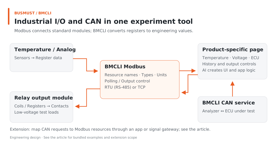
Figure 11-1. Connect resources first, then expand into shared displays and CAN coordination. Engineering relationship diagram.
Input for AI: Describe the Acquisition Tool
Section titled “Input for AI: Describe the Acquisition Tool”Begin with a defined teaching TCP slave: prepare tutorial-modbus-profile.yaml and start a matching slave at 127.0.0.1:15020, Unit ID 1. This task acquires Modbus data and demonstrates writing/reading a teaching coil. ECU signals and real relay coordination are later extensions.
Build a Modbus acquisition tool with BMCLI as the backend. I have prepared tutorial-modbus-profile.yaml and started a matching teaching TCP slave at 127.0.0.1:15020, Unit ID 1. Check Profile addresses, types, scaling, and units; read resources and initial values. Then sample Temperature every 500 ms and mark values stale after 1500 ms without updates. Generate a local page showing temperature, recent history, quality, and update time, with start/stop controls. In a separate operation area, allow only true/false writes to the teaching slave’s Enable coil and display requested and readback values. Verify normal response, no response, and recovery displays. Deliver the program, page, and a short check report. Writes are restricted to this teaching slave with no real load; do not control actual relays or connect CAN coordination.
AI checks the Profile, reads slave responses, creates polling, and generates the page. The bundled Profile and device list defines register layout; execution requires a matching slave. This TCP example needs no CAN analyzer and is suitable for learning interfaces on a development computer.
Finished Result: Converted Data
Section titled “Finished Result: Converted Data”The prompt asks AI for resource acquisition, a teaching-coil page, and a short report. The bundled Profile defines conversion rules; the following TCP slave data shows how engineering values appear.
Learn conversion with the teaching TCP slave before connecting bench equipment. Its endpoint is 127.0.0.1:15020, Unit ID 1, with these resource values:
| Resource | Address and type | Displayed result |
|---|---|---|
| Temperature | Holding 0,Uint16 × 0.1 | 1234 → 123.4 ℃ |
| Setpoint | Holding 2,Uint16 | 321 count |
| Enable | Coil 1,Bool | true |
| InputOnly | Input 0,Uint16 | 300 raw |
| Mode | Holding 3, enumerated | 1 → On |
BMCLI supplies named, unit-bearing data to the page. It also expresses update state:
| Experiment stage | Sample result |
|---|---|
| Slave responds normally | Temperature value, quality=good |
| Slave stops responding | Read error recorded, quality=bad |
| Slave recovers with raw 250 | 25 ℃, quality=good |
The last value before disconnection can remain for reference while the page clearly states whether it is still valid.
Implementation Explained: BMCLI’s Role in the Tool
Section titled “Implementation Explained: BMCLI’s Role in the Tool”The key calls below explain the implementation. AI-generated code organizes them into a complete workflow, processes responses, and handles cleanup.
How Acquisition Obtains Engineering Values
Section titled “How Acquisition Obtains Engineering Values”The program confirms module addresses, reads by resource name, and delegates continuous polling to BMCLI. These three steps follow.
Confirm Raw Registers
Section titled “Confirm Raw Registers”Use raw reads to check slave address, response length, and register values, then convert through the Profile into engineering values such as temperature.
# Read raw holding registers to verify slave address, returned length, and raw values.bmcli modbus read --transport=tcp --host=127.0.0.1 --tcp-port=15020 ` --unit-id=1 --table=holding-registers --address=0 --count=2 ` --format=jsonInterpret an Address as Temperature
Section titled “Interpret an Address as Temperature”After loading the Profile, read temperature by resource name. BMCLI interprets register type, scaling, and units so the page can use engineering values directly.
# Load the database as a named resource for later decoding or protocol operations.bmcli database load --file=tutorial-modbus-profile.yaml ` --name=tutorial-modbus --type=modbus-edgex# List resource names and types in the Profile.bmcli modbus resource list --database=tutorial-modbus --format=json# Read the Temperature resource to obtain converted temperature directly.bmcli modbus resource read --database=tutorial-modbus ` --resource=Temperature --transport=tcp --host=127.0.0.1 ` --tcp-port=15020 --unit-id=1 --format=jsonAcquire Continuously and Supply the Page
Section titled “Acquire Continuously and Supply the Page”Create a 500 ms polling job, then read latest values and history for display. The returned fields supply update times and quality notices; polling itself need not run in the browser.
# Create a 500 ms polling job with a 1500 ms stale threshold.bmcli modbus poll start --job=tutorial-temperature --interval=500 ` --stale-after=1500 --database=tutorial-modbus --resource=Temperature ` --transport=tcp --host=127.0.0.1 --tcp-port=15020 --unit-id=1 --format=json# Obtain the latest resource sample with time and quality.bmcli modbus value latest --job=tutorial-temperature --format=json# Read history after the selected sequence for incremental curve updates.bmcli modbus value history --job=tutorial-temperature ` --after=0 --count=100 --format=jsonThe daemon polls continuously, giving each result a sequence, timestamp, and quality. This example retains bounded history; clients read new records by sequence. Save results to files or a database for longer retention.
A Profile can also define compound commands such as Snapshot, returning several resources in one call to organize device state.
The daemon owns background polling. Prepare it before starting a job; modbus value latest/history reads that job’s samples. Stop the job created by this task when finished.
From Reading Resources to Controlling Outputs
Section titled “From Reading Resources to Controlling Outputs”For output controls, the application still calls BMCLI by resource name. The example below sets the teaching slave’s Enable coil to true. Because the Profile declares it readable/writable, BMCLI writes and reads back. Show requested value, communication result, and readback separately. For a real relay, add independent feedback according to module wiring.
# Write Enable=true to the unloaded teaching slave and read back the readable/writable resource.bmcli modbus resource write --database=tutorial-modbus ` --resource=Enable --value=true --transport=tcp --host=127.0.0.1 ` --tcp-port=15020 --unit-id=1 --format=jsonBefore adapting the teaching-coil interaction to a low-voltage bench, confirm output meaning, disconnection policy, and load conditions from the manual. Verify actions through both readback and actual output.
Connecting Real Equipment
Section titled “Connecting Real Equipment”Manual addresses such as 40001 are often display numbers; BMCLI uses zero-based protocol addresses. A manual/protocol address comparison table can save considerable first-integration time.
After establishing TCP, confirm Unit ID with a resource read. For writes, retain requested and readback values. Compound writes can partially complete; after an abnormal response, inspect current device values before choosing the next action.
Explore Further: Coordinate Industrial I/O with Automotive Buses
Section titled “Explore Further: Coordinate Industrial I/O with Automotive Buses”You can refine this example or extend it to other work. Choose a direction that interests you and discuss its implementation with AI.
Add External Measurements to the Same Scenario Plot
Section titled “Add External Measurements to the Same Scenario Plot”Ask AI to put ECU CAN signals and Modbus temperature/voltage resources on one page, showing engineering units and update times consistently. BMCLI handles decoding and polling; the application arranges curves by observation time and marks different sampling intervals and stale data. Add scenario transitions to show relationships between controller state and external quantities. Existing modules and configuration can supply experimental information missing from ECU messages alone.
Drive Low-Voltage Loads from CAN Requests
Section titled “Drive Low-Voltage Loads from CAN Requests”If the bench has Modbus relays, use the Unified Signal Gateway to map confirmed CAN requests to outputs. Define signal meanings, validity periods, and failure-output policy first, then verify request/write/feedback relationships on an isolated low-voltage bench. A successful write response confirms communication; independent feedback can confirm and display actual contacts or load state. CAN scenarios and standard modules then form an experiment with visible inputs, outputs, and results. Independent bench protection circuits retain equipment-protection interlocks.
Further Reading
Section titled “Further Reading”These references cover the interfaces used here; query local JSON Help for individual parameters.
Download this tutorial’s companion examples (ZIP)