
BUSMASTER CANopen: Connect nodes and load EDS
Applies to BUSMASTER 3.2.2.50. Screenshots use the Chinese interface; original UI labels are included where useful.
1. Before you start
Section titled “1. Before you start”Prepare BUSMASTER, a supported CAN interface, a wired CANopen peer that you can operate, its Node-ID and bitrate, and the matching vendor EDS/DCF.
| Item | Purpose | Check |
|---|---|---|
| CAN channel | Select the wired interface | CAN 1 is a locally assigned logical channel. Check channel configuration for its physical port. |
| Node-ID | Address a bus node, from 1 to 127 | The example uses 8. Manually adding a record adds an existing node to the local list. |
| EDS / DCF | Describe objects, types, permissions and PDO configuration | Use the file for the device model and firmware. Importing it loads the description, rather than writing device parameters. |
Teaching node and practice files
Section titled “Teaching node and practice files”Screenshots and values use teaching node 8, Classical CAN at 500 kbit/s and the default SDO route: request 0x608, response 0x588. An independent canopen-python 2.4.1 peer runs the teaching node with the objects below.
This page provides an EDS and initial data file. Use the EDS offline to browse objects and PDO definitions and practise saving a project. Online exercises require a running teaching node or a real CANopen device. For a real device, use its model- and firmware-specific EDS and select addresses, types and access permissions from its object dictionary.
| Teaching object | Type / access | Exercise and initial value |
|---|---|---|
0x1018:1 |
UNSIGNED32 / ro | Identity and repeated reads: 0x4255534D, raw bytes 4D 53 55 42 |
0x1017:0 |
UNSIGNED16 / rw | Heartbeat producer period: 500 ms, F4 01 |
0x2000:0 |
UNSIGNED32 / rw / PDO-mappable | Example value: 0x12345678, 78 56 34 12 |
0x2002:0 |
UNSIGNED16 / rw / PDO-mappable | Example mode: 9, 09 00 |
0x1400 / 0x1600 |
RPDO1 communication / mapping | COB-ID 0x208, asynchronous type 255; 0x2000:0 at 32 bits followed by 0x2002:0 at 16 bits |
0x1800 / 0x1A00 |
TPDO1 communication / mapping | COB-ID 0x188, the same six-byte mapping; the teaching node transmits periodically in Operational |
0x2100:0 |
DOMAIN / rw | File exercises: 6145 bytes initially; an initial-data file is provided for restoration |
The teaching model also provides signed integers, floating-point values and strings for further browsing.
The tool covers CANopen CC / CiA 301 on Classical CAN, with up to eight data bytes per frame. CANopen FD / USDO, an active LSS configuration master and a dedicated CiA 402 panel are outside this feature set. LSS frames can be decoded passively in the event list.
2. Find your way around the window
Section titled “2. Find your way around the window”Open CANopen in the top ribbon, next to XCP calibration (XCP 标定).
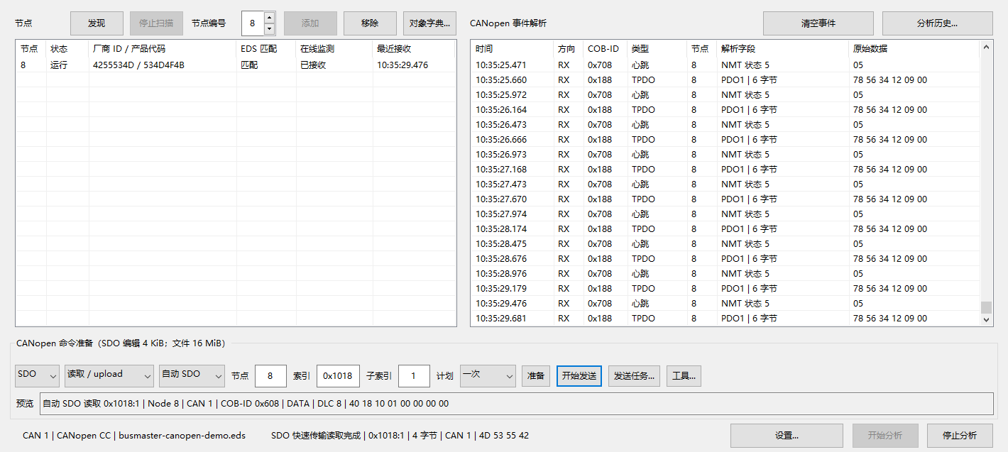
CANopen window: node 8 and the identity read result.
| Area | Purpose |
|---|---|
| Upper left: nodes | Discover, add and select nodes; inspect state, identity matching and most recent reception |
| Right: events | Inspect time, TX/RX, COB-ID, type, node, decoded fields and raw data |
| Lower area: command preparation | Select SDO/NMT/SYNC/TIME/PDO, address, value and send plan |
| Bottom: settings and status | Configure channel and monitoring, start/stop analysis and inspect transaction results |
Use Prepare → inspect the preview → Start sending in that order. Prepare again after changing the command, object or plan. TX and RX indicate transmit and receive directions. Confirm a successful read from the node response and completion result at the bottom.
Send tasks… (发送任务…) displays or stops repeated transactions. Analysis history… (分析历史…) filters retained events; see event analysis.
3. Connect CAN and start analysis
Section titled “3. Connect CAN and start analysis”- In the BUSMASTER main window, open Driver selection (
驱动选择) and select your CAN interface. - Open Channel configuration (
通道配置), identify the wired channel by its full device name and physical port, and match the node bitrate. This example uses Classical CAN at 500 kbit/s. - Check CAN_H, CAN_L, reference ground and termination, then click Connect (
连接). - Open CANopen → Settings… (
设置…). Select that channel under CAN channel; this example uses CAN 1. Select Heartbeat and initially retain the default monitoring and response timeout. - Set time display to System time (
系统时间), click Apply (应用), then Start analysis (开始分析). - Observe new RX events, node state and most recent receive time. A manually added row is a local node record.
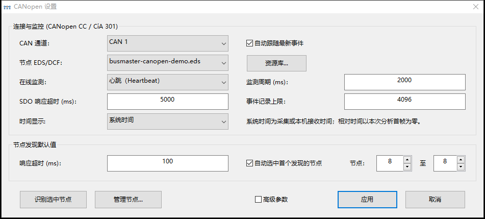
CANopen settings: monitoring, response timeout and time display.
Heartbeat selects BUSMASTER’s local monitoring method. The device configuration controls whether the device produces heartbeats and at what period. Set the producer period through 0x1017:0 when supported by the device.
Disabled monitoring and Heartbeat monitoring send no node-guarding requests. Node guarding sends guarding RTR frames at the configured interval. Choose the method supported by the device; Heartbeat is usually preferred.
Select the displayed time
Section titled “Select the displayed time”| Mode | Meaning |
|---|---|
| System time | Local computer timezone, HH:mm:ss.fff. BUSMUST USB-CAN(FD) uses capture time; other drivers fall back to local receipt time if capture time is unavailable. |
| Absolute time | Raw capture timestamp in seconds. Its origin depends on the driver, so a large seconds value can be normal. |
| Relative time | Time since the first observed frame on that channel in the current analysis session, rather than the interval since the preceding event. |
This setting controls the event list, most recent node reception and analysis history. It changes timestamp display; TIME transmission is covered under network commands. If there is no RX traffic, check the channel, bitrate, wiring and whether the peer is transmitting.
4. Discover or manually add nodes
Section titled “4. Discover or manually add nodes”Add a known Node-ID
Section titled “Add a known Node-ID”- Enter
8in the upper-left node number field and click Add (添加). - Select node 8, then check that the node field in the send area is also 8.
The add-node field and send-node field have different purposes. A duplicate number is not inserted twice; the Add button is disabled for an existing number.
Discover a range
Section titled “Discover a range”- Connect, start analysis and open Settings….
- Set the node discovery default range to 8 through 8 and apply.
- Click Discover (
发现), wait for completion and select the node. To interrupt discovery, click Stop scan (停止扫描).
Discovery actively reads identity objects in the range. If a node is not found, check for heartbeats and try a readable object listed in the vendor manual.
5. Import EDS and browse the dictionary
Section titled “5. Import EDS and browse the dictionary”Add a resource and bind it to a node
Section titled “Add a resource and bind it to a node”- Select node 8 and open Settings… → Resource library… (
资源库…). - In the EDS/DCF library, click Add… (
添加…) and selectbusmaster-canopen-demo.eds. For a real device, select its vendor file. - Select the added file and click Use selected (
使用选中项). - Back in settings, check the node EDS/DCF path and click Apply.
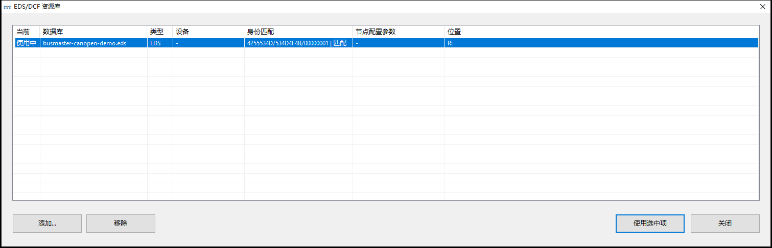
EDS/DCF library: select the description for the current node.
Browse definitions and online values
Section titled “Browse definitions and online values”- Select node 8 in the main window and click Object dictionary… (
对象字典…). - Check the CAN channel, Node-ID and EDS/DCF at the top. Find
0x1018:1and inspect its name, UNSIGNED32 type and ro permission. - For the first exercise, browse definitions, then close the window and continue to the next tutorial to read identity.
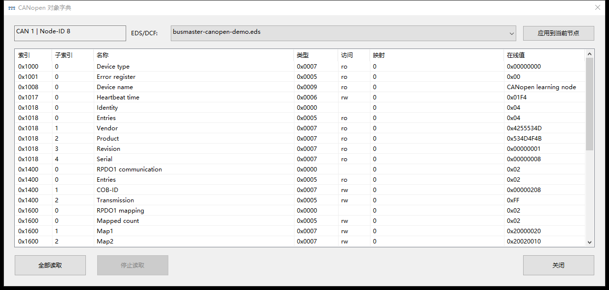
Object dictionary: types, access permissions and online values.
For a batch of online values, click Read all (全部读取); interrupt it with Stop reading (停止读取). Batch reading attempts every readable object in the file. The teaching node’s 0x2100:0 has 6145 bytes, exceeding the ordinary SDO editor’s 4 KiB capacity; use file SDO for it. If a batch reaches this object and reports a capacity failure followed by communication protection, follow SDO recovery before further small-parameter reads.
The upper dropdown can select another library file. Apply to current node (应用到当前节点) changes the binding; selecting a file alone performs no device read or write. Check each node’s binding individually. Type code 0x0007 is UNSIGNED32 and 0x0006 is UNSIGNED16; ro means read-only and rw means read/write.
Series home · Next: SDO parameters
Use the download center for current and archived BUSMASTER releases.