
BUSMASTER E2E: Select a profile and configure its parameters
Use the communication specification to choose the profile. This chapter first changes the DataID mode of the P01 frame from chapter 01, then configures the other built-in profiles.
1. Choose a built-in profile
Section titled “1. Choose a built-in profile”| Profile | Payload length (bytes) | Counter range | First counter by default | Main parameters |
|---|---|---|---|---|
| P01 | 2–30, fixed length | 0–14 | 0 | DataID, mode (BOTH/ALT/LOW/NIBBLE), CRC and counter positions, and the DataID nibble position in NIBBLE mode |
| P02 | 2–64, fixed length | 0–15 | 1 | 16 DataID bytes, fixed field layout |
| P04 | 12–64 | 0–65535 | 0 | 32-bit DataID, header offset and length range |
| P05 | 3–64, fixed length | 0–255 | 0 | 16-bit DataID and header offset |
| P06 | 5–64 | 0–255 | 0 | 16-bit DataID, header offset and length range |
Selecting a built-in profile can adjust the frame type, length and RTR. For example, default P04 settings can extend an 8-byte standard frame to a 12-byte FD frame, preserving the original data and padding with zeros. The software does not automatically shorten an existing longer payload. Set BRS according to the network. For a custom DLL, use the length and layout specified by its provider.
Classical CAN allows up to 8 data bytes. CAN FD allows 0–8, 12, 16, 20, 24, 32, 48 and 64 bytes. Intersect these lengths with the selected profile’s range. For example, P04 requires CAN FD and P01 cannot use a 32-byte payload.
2. Switch the P01 DataID mode
Section titled “2. Switch the P01 DataID mode”The transmit row’s CAN ID identifies the frame. DataID is entered separately, in hexadecimal, in the E2E settings. Whether any part of DataID appears directly in the payload depends on the profile and mode.
Clear Repetition and disconnect CAN before editing. Select the E2E settings for CAN ID 0x2A0. Start with DataID 0x0123, an eight-byte all-zero template, first counter 0, counter at 8 / 4 / Intel and checksum at 0 / 8 / Intel.
BOTH to LOW
Section titled “BOTH to LOW”- Enter DataID
0x23first and press Tab. LOW accepts only one byte. - Select and confirm LOW.
- Verify that DataID is
0x0023or0x23and the two field positions are unchanged. - Click Reset, connect CAN and send manually. Use reference values for LOW.
If the initial change to LOW is rejected, check the restored mode, commit the one-byte DataID and select LOW again.
LOW to ALT or BOTH
Section titled “LOW to ALT or BOTH”- Select and confirm ALT or BOTH first.
- Enter DataID
0x0123and press Tab. - Reset and send. ALT alternates the DataID bytes by counter value. BOTH uses both bytes.
To use the four reference payloads in chapter 01 again, restore all its parameters and start from counter 0.
Switch to NIBBLE
Section titled “Switch to NIBBLE”- Select NIBBLE. The nibble position field appears.
- Set DataID to
0x0123and press Tab. NIBBLE accepts0x000through0xFFF. - Enter nibble position
12and press Tab. Keep the counter at 8 / 4 / Intel and checksum at 0 / 8 / Intel. - Verify the three fields are disjoint. Reset, connect and send.
Bit 12 starts the high nibble of byte 1. It contains the low four bits of the high DataID byte, which is 1 in this example. The low nibble contains the counter. Byte 1 should read 10 and then 11 on the first two frames. Byte 0 contains the CRC for this mode.
3. Enter the 16 P02 DataID bytes
Section titled “3. Enter the 16 P02 DataID bytes”Add a separate 0x2A1 row and select AUTOSAR P02 under Dynamic Message. Keep 0x2A0 for P01. Select the P02 row to show its settings.
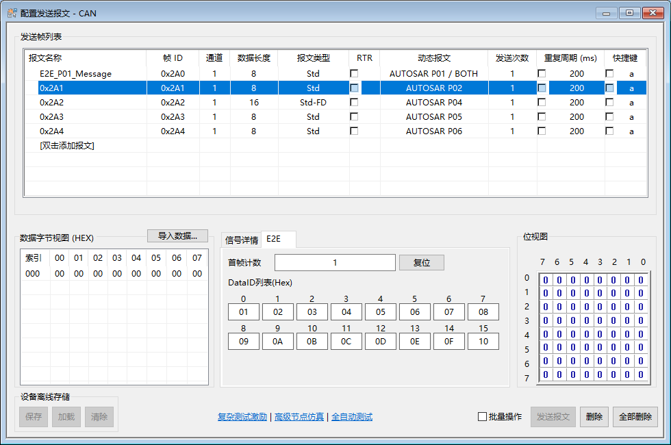
Figure 4. From left to right and top to bottom, the fields correspond to indices 0–15. Each field accepts one hexadecimal byte. The example uses 01 through 10 (hex).
P02 indexes this list by the counter. By default the first counter is 1, so the first frame uses index 1. If the peer expects the first counter to be 0, set it explicitly and calculate the corresponding reference payloads. Populate all 16 entries from the communication specification and confirm there are no input errors.
4. Configure and send P04, P05 and P06
Section titled “4. Configure and send P04, P05 and P06”Create a separate row for each algorithm. Disconnect CAN and clear Repetition on the teaching rows. Use logical channel 1, an all-zero template, send count 1 and RTR cleared. Use a CAN FD-capable peer for P04 with BRS disabled.
| Setting | P04 | P05 | P06 |
|---|---|---|---|
| CAN ID | 0x2A2 |
0x2A3 |
0x2A4 |
| Frame type | Std-FD, BRS disabled |
Std |
Std |
| Payload length | 16 bytes | 8 bytes | 8 bytes |
| Dynamic Message | AUTOSAR P04 | AUTOSAR P05 | AUTOSAR P06 |
| DataID (hex) | 0x12345678 |
0x0123 |
0x0123 |
| First counter | 0 | 0 | 0 |
| Header offset | 8 bits | 8 bits | 8 bits |
| Minimum / maximum length | 16 / 16 bytes | Uses the row’s 8-byte length | 8 / 8 bytes |
| Counter / checksum source | Manual | Manual | Manual |
- Set the ID, frame type, length, send count and Dynamic Message in the transmit list.
- Open E2E and enter the DataID and first counter. For P04 and P06, enter the minimum length in the left box and the maximum in the right box. Press Tab after each edit.
- Enter the header offset of 8 bits last and press Tab. Verify the derived fields below. Read-only fields are shown in grey.
- Reset the row, prepare the receiver, connect CAN and click Send Message twice. Verify the ID, frame type, length and both payloads.
- Disconnect before configuring the next row.
| Derived field (start bit / width / byte order) | P04 | P05 | P06 |
|---|---|---|---|
| Counter | 31 / 16 / Motorola | 24 / 8 / Intel | 40 / 8 / Intel |
| Checksum | 79 / 32 / Motorola | 8 / 16 / Intel | 15 / 16 / Motorola |
An offset of 8 bits moves the entire header by one byte. Byte 0 remains zero. P04 uses bytes 3–4 for the counter, P05 uses byte 3 and P06 uses byte 5.
| Profile | Counter | Complete payload (hex) |
|---|---|---|
| P04 | 0 | 00 00 10 00 00 12 34 56 78 B7 4B 5C 35 00 00 00 |
| P04 | 1 | 00 00 10 00 01 12 34 56 78 47 C5 A6 40 00 00 00 |
| P05 | 0 | 00 AA 72 00 00 00 00 00 |
| P05 | 1 | 00 CB CA 01 00 00 00 00 |
| P06 | 0 | 00 1B 4C 00 08 00 00 00 |
| P06 | 1 | 00 B1 1D 00 08 01 00 00 |
5. Check offsets, field lengths and edits
Section titled “5. Check offsets, field lengths and edits”P04, P05 and P06 headers are byte-aligned. Enter the header offset in bits and minimum and maximum payload lengths in bytes. Use the Intel or Motorola DBC convention to interpret each start bit. Ensure the protected fields fit and do not overlap application fields. For a DBC layout, follow chapter 03.
Press Tab to commit each edit. If you move two fields, check their final source, width and byte order before sending. If the software rejects an edit, check the restored values for range, overlap and payload bounds. Valid changes initialize a new counter sequence. Confirming an unchanged value or cancelling a selection keeps the existing count. Click Reset to start from the configured first value.
Previous: First protected frame · Series overview · Next: DBC signals
Use the download center for current and archived BUSMASTER releases.