
BUSMASTER E2E: Manage algorithms and build a custom DLL
Use E2E next to Database on the CAN ribbon to manage available algorithms. Choose an algorithm for a frame and set its layout in the transmit window.
1. Default algorithms
Section titled “1. Default algorithms”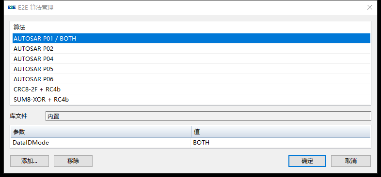
| Algorithm | How it works |
|---|---|
| AUTOSAR P01 / BOTH, P02, P04, P05 and P06 | Five built-in profiles. P01 supports multiple DataID modes. |
| CRC8-2F + RC4b | CRC-8, polynomial 0x2F, initial value FF, final XOR FF, no reflection. |
| SUM8-XOR + RC4b | Add the covered bytes, take the low eight bits and XOR with FF. |
Both bundled DLL examples use a four-bit rolling counter (RC4b) that wraps from 15 to 0. A new configuration offers all seven choices. An existing project retains its saved list, including an explicitly empty list. To restore an example, add it or use a separate new project for the exercise.
2. Use a bundled example
Section titled “2. Use a bundled example”Reuse the 0x2A1 standard eight-byte frame from chapter 02, or create a new row to keep the P02 example. Disconnect CAN, clear Repetition and use an all-zero template.
- Choose CRC8-2F + RC4b under Dynamic Message.
- In the row’s E2E tab, verify first counter 1, manual counter 48 / 4 / Intel and manual checksum 56 / 8 / Intel.
- Prepare the receiver, connect and send manually.
- Disconnect before switching to SUM8-XOR + RC4b. Use the same default layout.
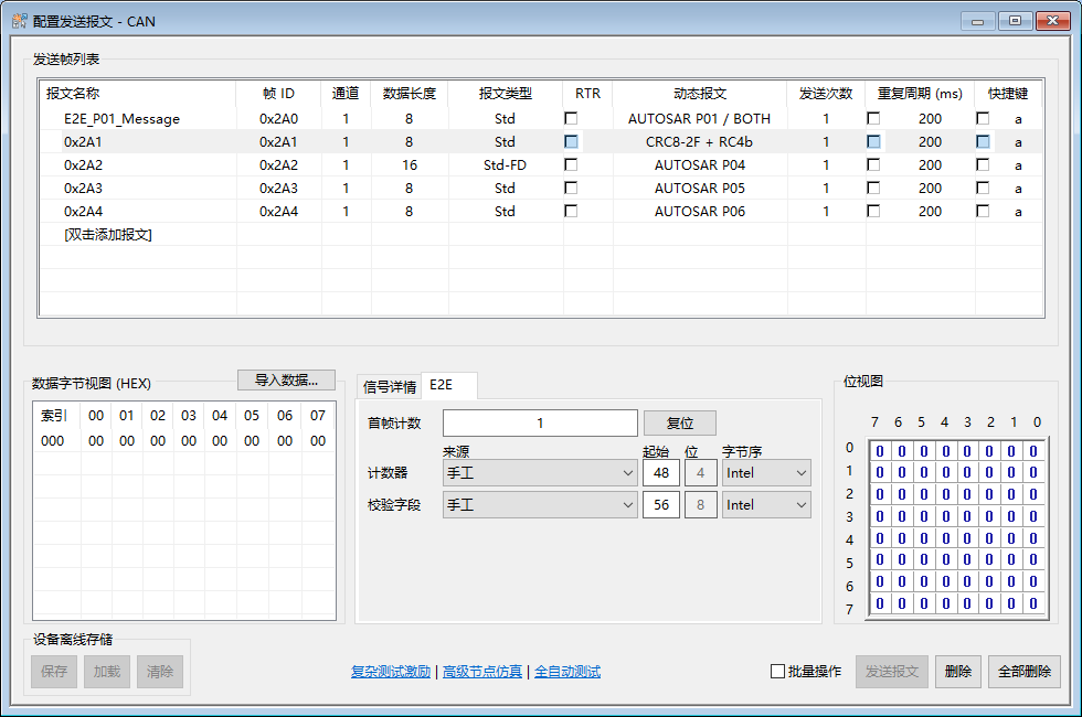
Figure 8. The DLL examples use no DataID. They write the counter to the low nibble of byte 6, then calculate the checksum over every payload byte except byte 7. The CAN ID is not included.
| Algorithm and frame | Complete payload (hex) |
|---|---|
| CRC8-2F, counter 1 | 00 00 00 00 00 00 01 45 |
| CRC8-2F, counter 2 | 00 00 00 00 00 00 02 34 |
| SUM8-XOR, counter 1 | 00 00 00 00 00 00 01 FE |
| SUM8-XOR, counter 2 | 00 00 00 00 00 00 02 FD |
The default counter starts at 1 on the wire. An explicit first value takes precedence, including 0. Reset restores the configured starting sequence.
3. Move the fields
Section titled “3. Move the fields”Change the start bits, byte orders and first counter in the transmit row’s E2E panel. The counter and checksum widths are fixed at four and eight bits. For a DBC source, the selected signal supplies the layout.
For SUM8-XOR + RC4b, stop periodic transmission and disconnect. Set first counter 3, counter 12 / 4 / Intel and checksum 0 / 8 / Intel. Leave other application bits zero. On reconnect, the first frame should be CF 30 00 00 00 00 00 00. Counter 3 occupies the upper nibble of byte 1, and 0x30 XOR 0xFF = 0xCF.
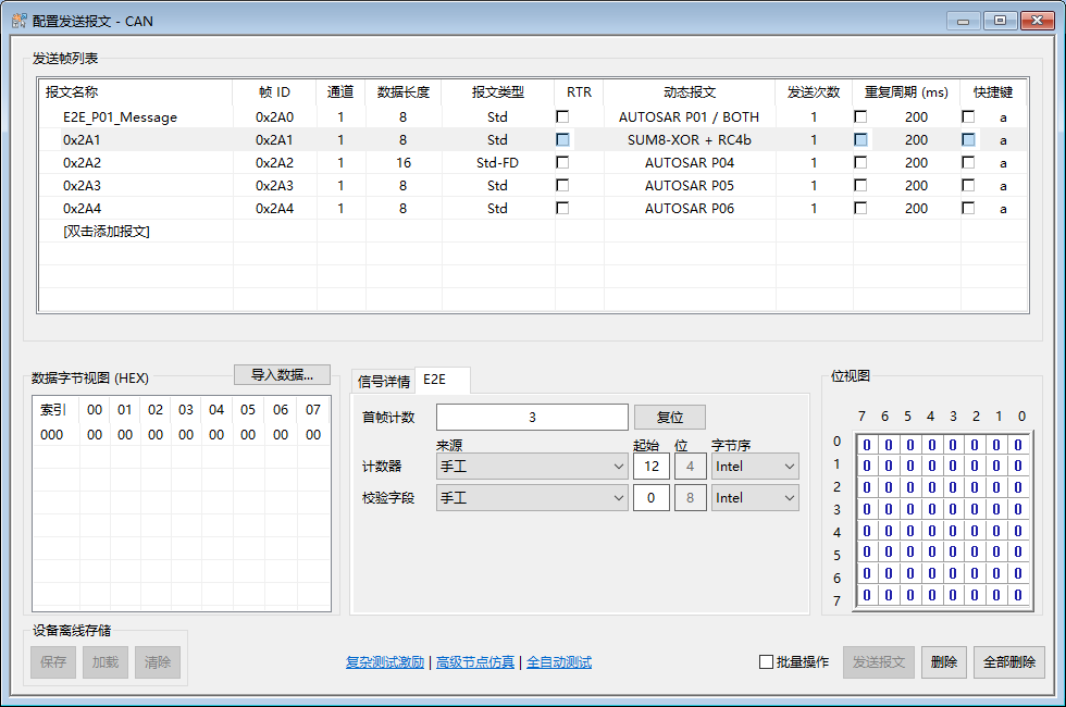
Press Tab to commit each edit. If a change is rejected, check the restored values for overlap and payload bounds. Use the Intel or Motorola bit convention defined for the project.
4. Manage the list of available algorithms
Section titled “4. Manage the list of available algorithms”Click Add and choose a built-in algorithm or select a DLL file. Edit the selected algorithm’s parameters and press Tab to commit each cell. Click OK to save the list or Cancel to discard the edits.
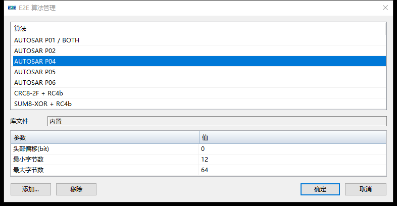
| Operation | Effect |
|---|---|
| Edit transmit row A | Only row A changes. |
| Edit an algorithm in the manager | The changes apply when the algorithm is selected again. Existing rows keep their copies. |
| Remove an algorithm from the manager | Removes it from the selection list. Existing rows retain the configuration and state. |
| Use one DLL in multiple rows | Each row has its own parameters, counter and Context. |
Removing an entry does not delete the DLL from disk. If an active DLL file is missing, protected transmission fails. To apply updated settings to a row, explicitly reselect the algorithm and check its fields. A change to the effective configuration starts a new counter sequence.
5. Build a custom DLL
Section titled “5. Build a custom DLL”Download the source and standalone projects, or use BMAPI SDK/example/e2e_counter_checksum in the installed SDK. The archive includes source, build projects, support files, licenses and a BMCLI example.
- Extract the archive to a writable directory and keep
supportalongside the projects. - In Visual Studio Installer, select Desktop development with C++, the MSVC v142 x86/x64 build tools and the Windows 10 SDK.
- Open
E2E_Algorithms.sln, select Release / Win32, and build the solution. - Find
crc8_2f_rc4b.dllandsum8_xor_rc4b.dllunderbin/Release/. - Open E2E → Add, select a DLL file, check the displayed metadata and parameters, then save. Select the new entry in a transmit row, configure its layout and verify the received frames.
The projects are independent of the BUSMASTER solution and use the static C runtime. Match the DLL architecture to the 32-bit BUSMASTER process.
| Task | File or interface |
|---|---|
| Project entry points | crc8_2f_rc4b.c and sum8_xor_rc4b.c |
| Checksum and common protection code | calculate_checksum in counter_checksum_impl.h |
| Context and layout contract | support/bm_e2e_plugin_api.h and the archive README |
| Export | Preserve BM_E2E_GetPluginApi. Assign a new provider identity for a new algorithm or incompatible configuration. |
See the included COPYING files for licensing.
6. Set DLL parameters and enable the SUM8 toggle bit
Section titled “6. Set DLL parameters and enable the SUM8 toggle bit”The manager’s parameters configure the algorithm. Set the first counter and field layout in the transmit row.
| Setting | Example value |
|---|---|
| Profile / Variant | 1 / 0 for both DLLs |
| Context bytes | 16 bytes of per-row state for both DLLs |
| Config | layout-v1, which supplies start bits, widths and byte orders |
| Hex parameters | CRC8 uses 01 2F FF FF: version, polynomial, initial register, final XOR. SUM8 uses 01 00 00 00: version, toggle enable, low and high bytes of the LSB0 bit position. |
| Extra writable bits | Leave blank by default. To enable the toggle bit, declare it separately from the counter and checksum. |
These values apply to the bundled examples. Use the provider’s documentation for other DLLs.
Toggle bit 16
Section titled “Toggle bit 16”Use an eight-byte all-zero template, default counter 48 / 4 / Intel, checksum 56 / 8 / Intel and send count 1.
- Stop periodic transmission and disconnect CAN. In the E2E manager, select SUM8-XOR + RC4b.
- Enter
00 00 01under Extra writable bits and press Tab. This hexadecimal byte mask authorizes bit 0 of payload byte 2. Unspecified mask bytes are zero. The counter and checksum are included throughlayout-v1. - Set the hex parameters to
01 01 10 00and press Tab. The second byte enables the toggle and10 00specifies LSB0 bit 16 in little-endian order. Keep Configlayout-v1, Profile 1, Variant 0 and Context 16. - Save the manager’s settings. Reselect SUM8-XOR + RC4b under Dynamic Message to copy the updated settings to the transmit row.
- Set first counter 1 and verify the default field positions. Click Reset, connect and send twice.
| Frame | Complete payload (hex) | Toggle and counter |
|---|---|---|
| 1 | 00 00 01 00 00 00 01 FD |
Byte 2 bit 0 is 1, counter 1 |
| 2 | 00 00 00 00 00 00 02 FD |
Byte 2 bit 0 is 0, counter 2 |
The toggle continues 1, 0, 1, 0. Both checksums above are FD because the covered byte sums are equal. To disable it, disconnect, restore 01 00 00 00, clear the extra writable mask, save and reselect the example in the row.
The archive’s counter-checksum.bmgw uses the same build outputs from bin/Release/ on 32-bit Windows BMCLI versions that support external E2E with accepted-v1 and contract_version. BMCLI 1.6.5 build 151 does not support this exercise. The sample uses the network e2e-demo and IDs 0x2A7 and 0x2A8. Follow the archive README and your BMCLI version’s help for network binding and commands.
Previous: DBC signals · Series overview · Next: Periodic transmission and saving
Use the download center for current and archived BUSMASTER releases.