
BUSMASTER XCP: Configure the workset and physical-value curves
Applies to BUSMASTER 3.2.2.50. Screenshots use the Chinese interface.
4. Add the workset and configure physical-value curves
Section titled “4. Add the workset and configure physical-value curves”- Search for
EngineSpeedon the left, select the MEASUREMENT object and click Add >>. Then search forSpeedLimitand add the CHARACTERISTIC object. - Check that the workset on the right contains exactly these two objects and that Acquire is checked for both. A2L defines each object’s type, unit and access permission.
| Object | Role | Meaning in this example |
|---|---|---|
| EngineSpeed | Measurement, R | Engine speed in rpm, changing while the simulator runs. |
| SpeedLimit | Writable calibration, R/W | Engine speed limit in rpm, used to practise writing and reading back a scalar parameter. |
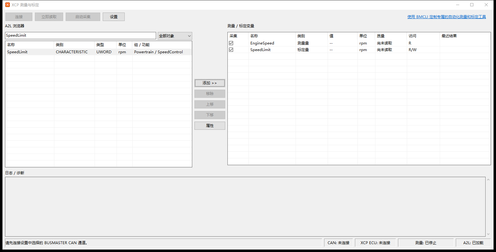
EngineSpeed and SpeedLimit in the workset; quality is “not yet read” before connection.
Signal Graph configuration is available while the main CAN connection is disconnected. Add physical-value elements and size the buffer before connecting the ECU:
- Click × at the top right of the XCP window to return to the main interface. The workset remains in the current project.
- Open CAN → Signal Graph → Configure, then click Configure Signals in the signal-curve configuration window.
- In the element selector, expand XCP → TEST_ECU → EngineSpeed → Physical Value, select Physical Value, and click Add. Add SpeedLimit → Physical Value in the same way.
- Check that the element list on the right contains both variables. Click OK to return to curve configuration, then OK again to return to the main interface.
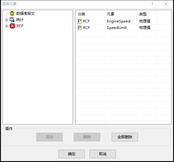
Both physical-value elements have been added to the CAN Signal Graph.
Physical Value displays the result of A2L conversion. Here, physical value = raw value + 5; a raw SpeedLimit value of 300 therefore appears as 305.
Open the CAN Signal Graph window and click Configure in the graph area to set the buffer size. The default is 5000 points, with a range of 1000–10000. All elements in the same bus graph share this capacity. New samples replace the oldest samples when the buffer is full.
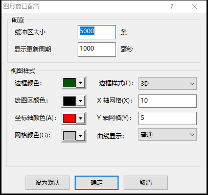
Graph window configuration: the default 5000-point capacity is shared by both variables.
Choose capacity based on variable count, sample rate and the duration you want to retain. Here, two variables updating about every 10 ms produce about 200 points per second in total; the default capacity retains roughly the latest 25 seconds. Return to the main interface when configuration is complete and continue with connection.
Series overview · Previous: Environment and A2L setup · Next: Reading and DAQ
Use the download center for current and archived BUSMASTER releases.