
BUSMASTER CANopen: Configure PDOs and exchange process data
Applies to BUSMASTER 3.2.2.50.
10. Configure PDOs and check process data
Section titled “10. Configure PDOs and check process data”PDO names use the node’s perspective: RPDO is received by the node; TPDO is transmitted by the node. The teaching RPDO1 and TPDO1 each map two objects into six bytes.
Read the device configuration
Section titled “Read the device configuration”- Select node 8, check the teaching EDS binding and select Once.
- Select PDO, then Prepare → PDO configuration… (
PDO 配置…). - Select RPDO1 declared in the EDS and click Read from node (
从节点读取). Check COB-ID0x208, enabled state, transmission type 255 and the two mappings. - The mapping order is
0x2000:0 / UNSIGNED32 / 32 bits, then0x2002:0 / UNSIGNED16 / 16 bits. Check that online validation matches the current node.
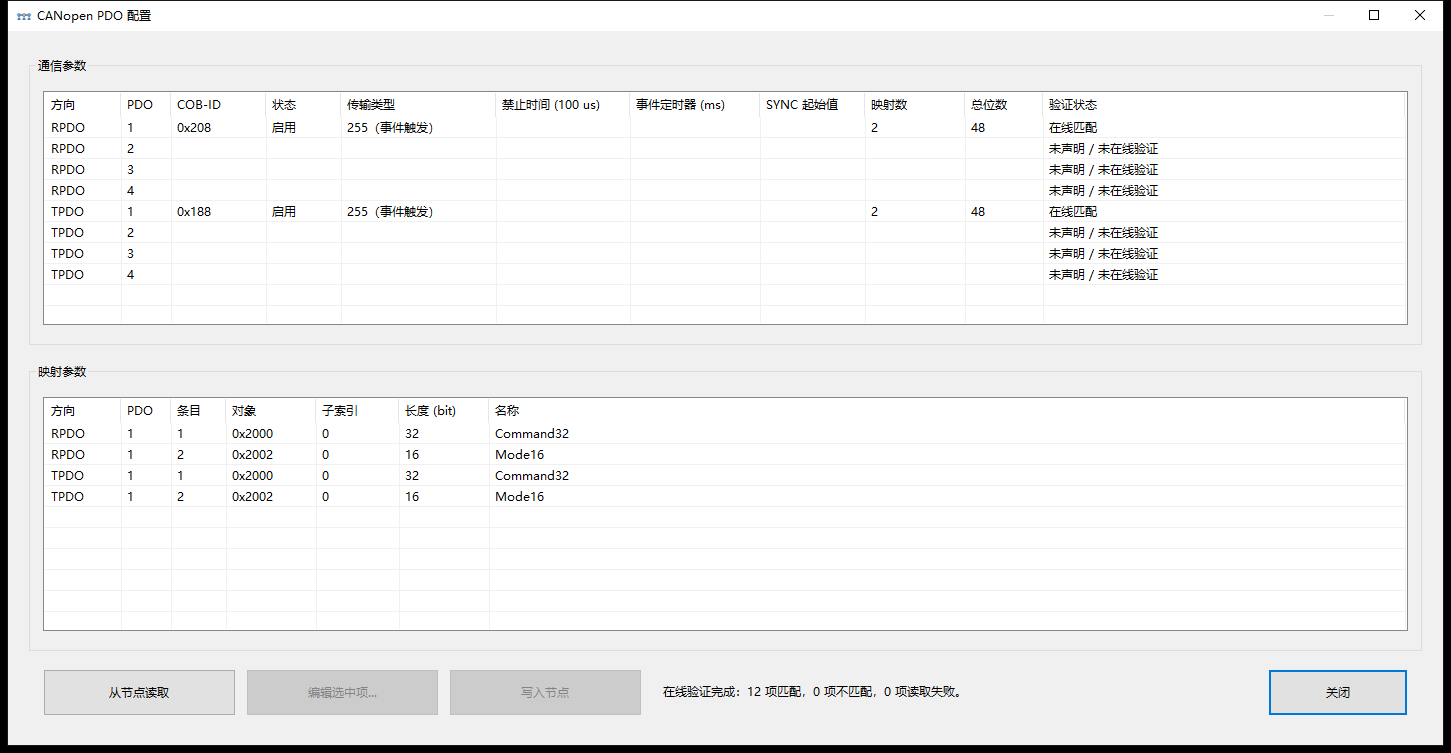
RPDO1 communication parameters and mappings read from the node.
Edit, write and read back
Section titled “Edit, write and read back”- Record the original communication parameters and mappings. Put the device into the configuration state required by its vendor, usually Pre-operational.
- Select a declared PDO, click Edit selected… (
编辑选中项…) and inspect the draft. Change the fields needed for the exercise. - Click Write to node (
写入节点) and wait for writing and readback to complete. - Written items match readback (
写入项已回读一致) means the fields written in this operation match the returned values. - Use Read from node again to check the actual fields. Restore and read back the recorded original configuration after practice.
Select PDOs declared in the EDS that the device supports editing. Follow the device requirements for dynamic or variable mapping and configuration state; static mappings may be fixed.
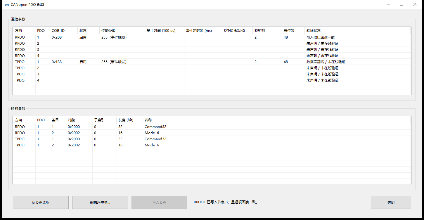
RPDO1 result: the written fields match their readback values.
Send RPDO1 and read the objects
Section titled “Send RPDO1 and read the objects”- Close configuration. If the node is Pre-operational, use NMT Start node and confirm Operational in a new heartbeat.
- Record the original values of
0x2000:0and0x2002:0. Select PDO and Once. - Enter every mapped field:
0x2000:0=123; 0x2002:0=456. - Click Prepare and select RPDO1. Expect COB-ID
0x208and six bytes7B 00 00 00 C8 01in the preview. - Start sending and inspect the frame in events. Read
0x2000:0and0x2002:0using SDO; the teaching node should return 123 and 456. - Restore the original values using SDO or the same PDO mapping and read them back. Teaching initial bytes are
78 56 34 12and09 00.
You can also enter the same six raw bytes directly.
Receive TPDO and optionally request it with RTR
Section titled “Receive TPDO and optionally request it with RTR”The teaching node periodically sends TPDO1 in Operational at COB-ID 0x188, carrying the same six-byte mapping. The event list shows the PDO number and raw bytes frame by frame; compare them with SDO readback to check byte changes.
For a device that supports RTR, select the corresponding TPDO RTR request in the PDO preparation menu. Check COB-ID, the RTR flag and Once, send, then wait for the TPDO data frame and inspect its payload. Availability depends on communication parameters, the RTR prohibition bit and device implementation. The teaching peer provides periodic TPDO but no RTR response; use a vendor-confirmed RTR-capable device for that branch.
For address conflicts, a disabled PDO or inconsistent mappings, return to PDO configuration and check the read-back COB-ID, enabled state, mappings and bound EDS.
Series home · Previous: tasks and network · Next: file transfer
Use the download center for current and archived BUSMASTER releases.