
Unified Signal Gateway: Connect Different Buses with One Signal Model
BMCLI’s Unified Signal Gateway exchanges signals with engineering meaning across buses, handling decoding, mapping, and re-encoding. A one-way connection from chassis CAN to a private development CAN illustrates configuration-only signal adaptation.
Imagine developing a sensor ECU that needs chassis speed but whose software is not yet ready to connect directly to the chassis network. Chassis CAN supplies speed in km/h; the ECU’s private CAN uses its own ID, layout, and m/s units. Connect one analyzer port to each side. BMCLI extracts chassis speed and re-encodes it on the private side, with no output from the private network back to chassis configured in the project.
Compared with forwarding complete frames, this exchanges selected signals and handles scaling, validity, periods, and target protection fields. AI generates native gateway configuration from both DBCs and your rules. Stable operation needs neither another script nor an AI session kept online.
Keep the two networks independent. Connect the chassis side according to project requirements and configure separate power and termination on the private side. Select electrical isolation according to analyzer specifications and the wiring design.
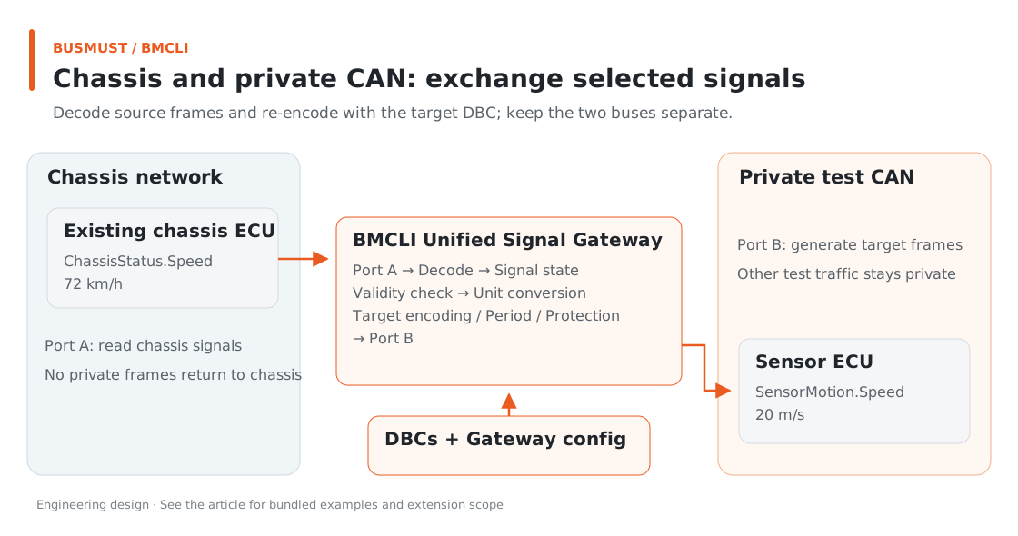
Figure 12-1. Two independent CAN networks exchange selected signals only. Engineering relationship diagram.
Input for AI: Describe the Dual-CAN Adaptation Project
Section titled “Input for AI: Describe the Dual-CAN Adaptation Project”Prepare both DBCs, project Bench, source-failure rules, and target protection rules. This task is limited to a teaching dual-CAN gateway; production E2E adaptation is a separate task using project specifications.
Use BMCLI’s signal gateway to generate a dual-CAN speed adaptation project for my sensor. chassis uses chassis.dbc and sensor uses sensor.dbc; configure devices and bitrates through project Bench. Extract ChassisStatus.Speed, convert to m/s, and write SensorMotion.Speed, transmitting the target every 20 ms. If the source has not updated for over 100 ms, emit the agreed invalid code and clear validity; restore valid speed when updates resume. Use my teaching rules for target Counter and CRC. Keep the networks independent and permit only specified chassis-to-sensor outputs, with no private-to-chassis transmission relationship. Use the confirmed Bench mode on the chassis side. Implement mapping with databases and native .bmgw configuration, without a custom program. Generate and validate offline first, then capture both sides on my confirmed isolated bench to check normal, invalid, and recovered behavior. Deliver the project, check results, and Linux deployment instructions.
The key questions are which signal, from where to where, and under what representation rules. DBC provides widths, byte order, and scaling. Supply project information for missing periods, invalid-value meanings, and E2E algorithms. AI does not require you to write every JSON field first.
The bundled dual-CAN gateway project and two DBCs use .bmgw, BMCLI’s native project format, to store logical ports, signals, and outputs. Bench still manages local connection details such as serial numbers.
Finished Result: Give the Sensor Speed It Understands
Section titled “Finished Result: Give the Sensor Speed It Understands”The native .bmgw project and both DBCs are included. The table below shows the configured mapping; later sections cover offline checking, bench execution, and Linux deployment.
Start with an experiment similar to real integration but easy to observe:
| Preparation | Role in the experiment |
|---|---|
| Computer, or Raspberry Pi with a matching Linux/ARM package | Run BMCLI and the gateway project |
| At least two suitable BUSMUST CAN/CAN FD ports | Connect separately to chassis and the sensor’s private network |
| Chassis speed source and sensor receiver | Test nodes can substitute for independent practice |
| Both DBCs, connection parameters, and protection specification | Define signal positions, units, periods, and validity |
The sides remain separate CAN networks. BMCLI generates the configured target messages so the sensor receives the signals it needs directly.
Source ID 0x100 uses km/h; target ID 0x200 uses m/s and transmits every 20 ms. The relationship is straightforward:
| Chassis speed | Sensor-side speed | Target state |
|---|---|---|
| 0 km/h | 0 m/s | Valid |
| 36 km/h | 10 m/s | Valid |
| 72 km/h | 20 m/s | Valid |
| 108 km/h | 30 m/s | Valid |
| No source update for over 100 ms | Invalid encoding | Valid=0; target protection continues normally |
For example, 72 km/h is source raw 7200 and target raw 2000. Encoding changes while physical meaning stays the same. When the source expires, the target explicitly reports no reliable current speed instead of presenting an old value as still updating.
Implementation Explained: BMCLI’s Role in the Tool
Section titled “Implementation Explained: BMCLI’s Role in the Tool”The key calls below explain the implementation. AI-generated code organizes them into a complete workflow, processes responses, and handles cleanup.
The Gateway Understands Signals, Not Just Frames
Section titled “The Gateway Understands Signals, Not Just Frames”The process is:
Source frame → decoding and validity checks → signal state → mapping and transformation → target encoding and protection → target transmission.
Frame routing suits forwarding existing frames. A signal gateway can select a single signal and place it in a different layout or protocol. BMCLI continuously performs several key jobs:
Common engineering values. Source and target each have their own codecs. Between them, state retains type, physical value, validity, and source observation time. Identical bits need not mean identical things, and recalculation does not refresh expired data. This example uses y=x÷3.6.
Independent output timing. Source arrivals update state; the target encodes and transmits on its own 20 ms period. Other policies suit updates on value changes. Choose by target protocol requirements, not the web page’s refresh rate.
Protection fields. Source checking and target protection have separate contexts. After target re-encoding, generate its own counter and checksum instead of copying source CRC. This example configures teaching target CRC/Counter only; projects with source protection should configure the matching check.
AUTOSAR E2E and vendor rules can integrate through matching configuration or plugins. AI uses the algorithm specification, Data ID, layouts, and test vectors to select CRC/SUM protection and complete configuration and verification, keeping counter/checksum rules together.
The offline check is ready to run:
# Validate native signal-gateway configuration offline without opening devices or transmitting.bmcli gateway validate --file=sensor-speed.bmgw --format=jsonThe bundled project’s check result is:
{"status":"ok","project":"sensor-speed","signals":2}On a bench with daemon, Bench, and channels prepared, AI organizes load, start, and observation:
# Load the dual-CAN signal-mapping project and prepare its runtime instance.bmcli gateway load --file=sensor-speed.bmgw# Start the configured one-way mapping and periodic target transmission.bmcli gateway start --instance=sensor-speed# Inspect source signals, mapped values, and validity to verify engineering meaning on both sides.bmcli gateway signals --instance=sensor-speed --format=json# Query gateway instance state and runtime statistics.bmcli gateway status --instance=sensor-speed --format=json# Stop this instance's mapped output and end the run.bmcli gateway stop --instance=sensor-speedThese commands show the key stages. A real tool also captures the target bus to check units, periods, invalid state, and protection, then cleans up its resources after stopping. Structural validation proves configuration is understood; target reception proves adaptation meets expectations.
Put the Gateway on a Raspberry Pi
Section titled “Put the Gateway on a Raspberry Pi”This need not occupy a desktop computer indefinitely. With architecture-matched BMCLI/BMAPI packages, a Raspberry Pi or compact Linux host can sit beside the bench and analyzer, running the same logical project. Change local Bench bindings; for native plugins, prepare matching ARM/Linux libraries too.
Ask AI to configure service startup, log rotation, state monitoring, and recovery, with a browser for status. BMCLI executes stable mappings without a continuously connected AI session or cloud decisions for every frame.
A dedicated Linux host helps standardize background load, deployment, and startup. Check end-to-end latency, jitter, and overload behavior against project metrics, and select a host/analyzer suitable for sustained operation, power, and environment requirements.
Explore Further: What a Unified Model Enables
Section titled “Explore Further: What a Unified Model Enables”You can refine this example or extend it to other work. Choose a direction that interests you and discuss its implementation with AI.
Expand from Dual CAN to Different Protocols
Section titled “Expand from Dual CAN to Different Protocols”BMCLI’s signal gateway supports CAN/CAN FD and Modbus endpoints. Import CAN definitions through DBC or configure Modbus resources—for example, output temperature samples to CAN or map CAN requests to a Modbus relay.
Processing extends beyond scaling: threshold comparisons, fixed mathematical functions, and coordinate transforms can form signal relationships. AI can generate and test plugins for more complex nonlinear algorithms or vendor encoding. This article’s dual-CAN mapping uses only databases and .bmgw configuration, making it a no-code application. A custom algorithm plugin is a code extension, even when AI writes it.
From Connecting Devices to Organizing a Signal System
Section titled “From Connecting Devices to Organizing a Signal System”Writing a separate converter between every new device and every existing one quickly creates many pairwise adapters. A unified model offers another approach: each connection interprets its own data, the application organizes relationships in a shared signal layer, and target endpoints express the required formats.
The same measurement meaning can serve instrument display, test judgment, and another bus’s input. The same application relationship can move from a desktop bench to an edge host. Reusing signals and application logic reduces repeated development as devices are added.
Replace Devices While Preserving Application Meaning
Section titled “Replace Devices While Preserving Application Meaning”If temperature initially comes from a CAN sensor and later a Modbus module, must the UI and tests be rebuilt? Ask AI to preserve the temperature name, units, and validity contract in the unified model, changing only source bindings and required conversion. Compare ranges, update periods, and invalid values first, then check existing mappings and pages still meet requirements. This separates hardware differences from application rules and develops signal interfaces reusable across hardware changes.
Define Trustworthy Conditions for Multisource Calculations
Section titled “Define Trustworthy Conditions for Multisource Calculations”When fast CAN signals and slower Modbus samples enter one calculation, two numbers alone are insufficient: their observation times also matter. Ask AI to define maximum input ages, allowed observation-time differences, and invalid-output behavior around unified signal state. Express suitable parts through built-in transformations and implement more complex fusion in plugins, checking different arrival orders and missing inputs. The model then specifies both what is calculated and when it is usable, providing a clearer basis for cross-protocol control and analysis.
Further Reading
Section titled “Further Reading”These references cover the interfaces used here; query local JSON Help for individual parameters.
Download this tutorial’s companion examples (ZIP)