
Signal Generation
Signal Generation allows the user to configure each signal in database messages with particular waveform and send the messages with these signal values at a particular sampling time period..
Each Signal can have different waveform settings allotted like Signal type, Amplitude, Frequency.
All the signals will be having a standard sampling time at which their amplitude will be calculated depending on the wave type and they will be sent out.
Currently only two waveforms are supported, Sine Wave and Triangular Wave.
To configure signals, go to menu option, CAN –> Signal Graph –> Configure and user will be shown with the following dialog box.
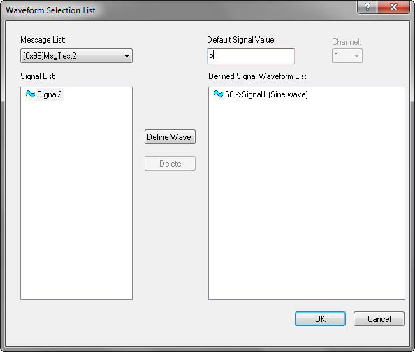
The above shown figure contains the list of all the messages in a combo box, “Message list:” which are present in currently selected database file.
“Signal List” List control shows the signals in currently selected message in combo box which are not defined with any waveform.
“Defined Signal Waveform List” List control shows all the signals in different messages for which the waveforms are defined.
Use the “Define Wave” button to define a waveform for a particular signal. Alternatively double click on the unselected signals can be used to do the same. When user triggers this event, the following dialog pops out.
Currently there are 4 types of waves supported:
-
Sine Wave
-
Cos Wave
-
Triangular Wave
-
Sawtooth Wave
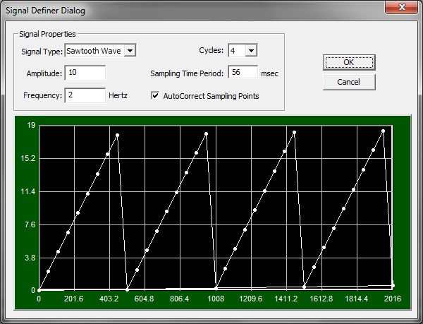
The dialog will be loaded with default waveform settings i.e. a sine wave with amplitude 10, frequency 1 and sampling time period 125. User can make appropriate changes to the wave by choosing signal type, desired amplitude and frequency. “Ok” button click will add the signal to Defined signals list.
The sampling Time Period which is last modified will be applicable to all the signals. For example, if for first signals you choose the sampling time period as 125 and for the second signal, you choose the sampling time period as 100. Then the sampling time period applicable is 100 for first and second signals.
“AutoCorrect Sampling Points” checkbox when checked, will calculate the sampling time period for a given frequency such that there will be at least 8 points in the a cycle and the graph does not distort.
Maximum frequency that can be set is 125 and Sampling Time Period is 32767
Now, if user wants to transmit the defined signals, make sure the application is in connected state and use the menu option CAN –> Waveform Messages –> Enable.
Alternatively user can use the toolbar items shown below for configuring and sending waveform signals.

Use the “Delete” button in Fig. 1 to delete previously configured signals defined signals list.
The Waveform Signals defined are saved along with configuration.
Authoritative source: BUSMASTER DITA help source signal_generation.dita, compiled into BUSMASTER.CHM with the application.